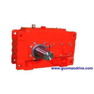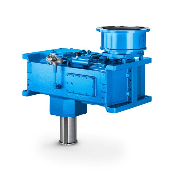


to Twostage gear unit sizes to Twostage gea B3-VH-12-D Bevel-helical gear boxes B3
In stock
SKU
B3-VH-12-D
$40,714.29
Flender/Flender Gear Units/Bevel-helical gear boxes B3
on. This provides scaffolding for hypoid gear set in which, starting from the mean point , the pitch cones of the pinion and wheel span common plane of contact and the gear axes do not intersect but cross at centre
  distance (see Fig. 2.. The associated pitch angles depend not only on the gear ratio and shaft angle (as in
  the special case of non-offset bevel gears), but also on the offset, tool radius and other factors. The pitch angle
  can only be calculated iteratively (see Sect. 2.3.2 ). The mean point is also termed the calculation or design point. Fig. 2.1 Hypoid gear set3 2 Fundamentals of Bevel Gears 2.2.5.3 Pressure Angle The pressure angles (see Sect. 3. chosen for bevel gear set will be referred to below as design pressure angles . They are not necessarily identical on both tooth anks. In particular, hypoid gears are made with different pressure angles on the drive and coast sides (see Sect. 2.2.4.5 ) in order to balance the sliding conditions on the two anks. In general, the smallest theoretically feasible pressure angle is not equal to 0/C1, si nt case of cylindrical gears and non-offset bevel gears, but is rather equal to the limit pressure angle lim. It is highly dependent on parameters such as the hypoid offset, spiral angle and tool radius (see Formula (2.). In this formula, expression m1sin m1Rm2sinm2 may become zero for certain hypoid gear designs, in which case the limit pressure angle will also be lim0/C1. However, when limis not equal to 0/C1, sliding conditions and paths of contact on the drive and coast tooth anks become different. This can be compensated by adding or subtracting the amount of limto or from the design pressure angles on the drive and coast anks respectively. An inuence factor of the limit pressure angle limis introduced so that the full amount of the limit pressure angle need not always be taken into account when calculating the blade angles of the tool. This is done partly because it is not always simple to ch
| Model Type | Bevel-helical gear boxes B3 |
|---|---|
| Gear Type | Bevel Helical Gear |
| Weight (kg) | 1900.000000 |
| Ratio Range | 1 : 16…90 |
| Low Speed Output | Solid shaft with parallel key acc. to DIN 6885/1 with reinforced spigot |
| Nominal Torque | 77200 Nm |
| Mounting Arrangements | Horizontal mounting position |
| Manufacturer | N.V. Flender Belge S.A. |
| Country of Manufacture | Bahamas |
| Data Sheet & Drawings | to Twostage gear unit sizes to Twostage gea B3-VH-12-D Bevel-helical gear boxes B3 |
Related Products