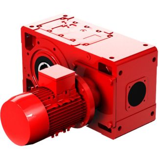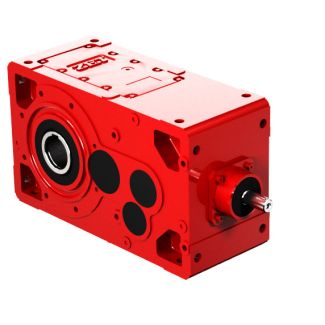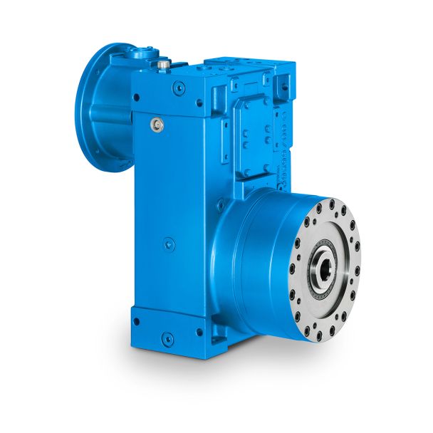

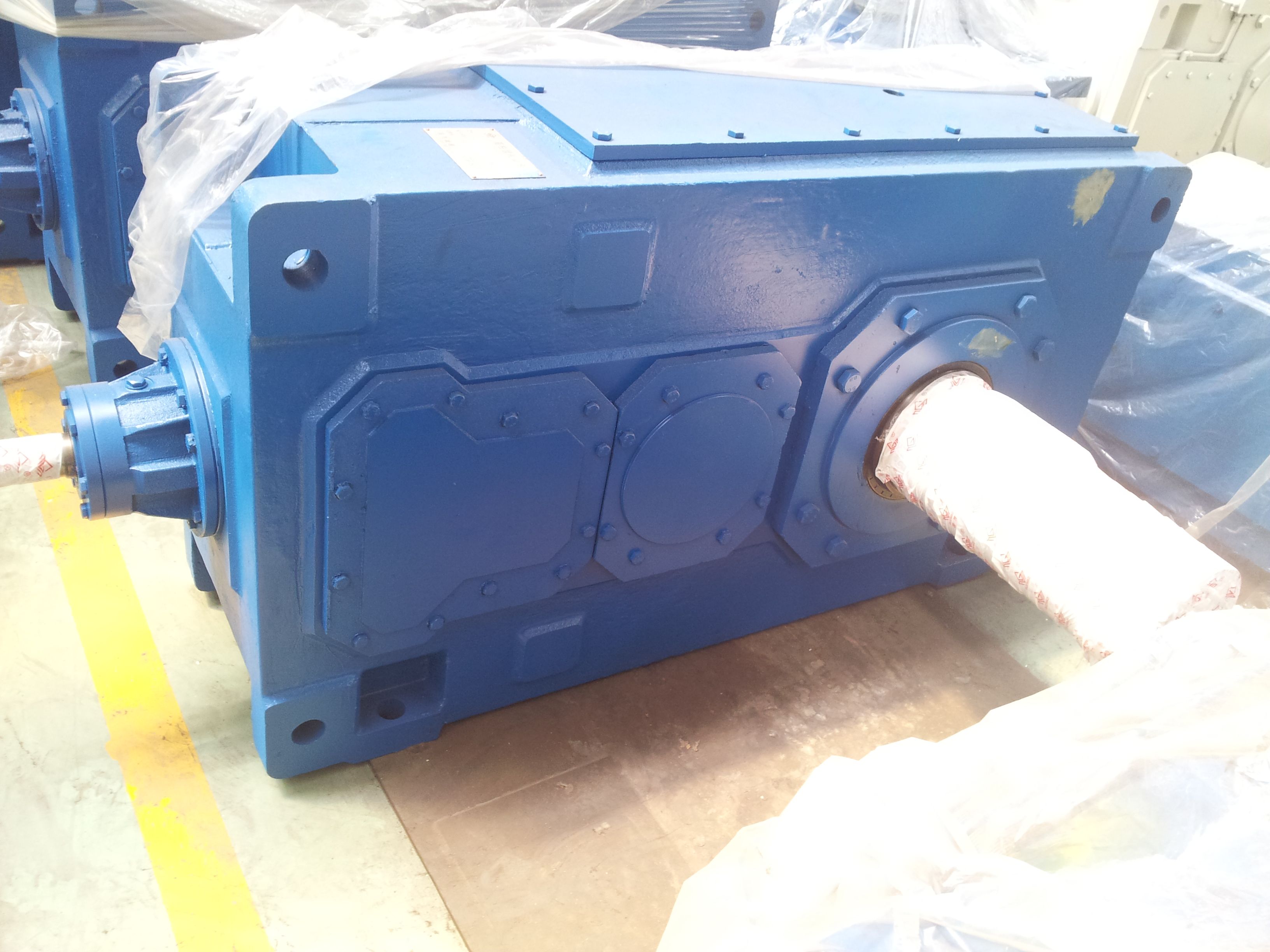
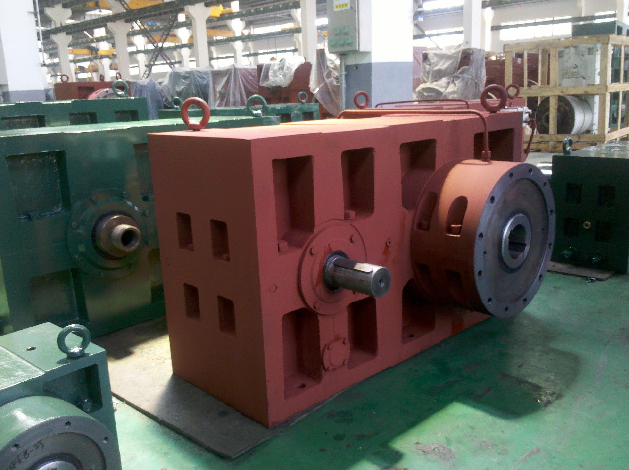
Bevel-helical gear Reduction Boxes B3 radial shaft sealHigh speed shaft HSS with Tacon B3-SH-20B
In stock
SKU
B3-SH-20B
$173,571.43
Flender/Flender Gear Units/Bevel-helical gear Reduction Boxes B3
ocket wheel 8 mm 7 mm 7 mm 7 mm Chain speed 1.4 / 1.2 / 1.1 / 1,2 / Bucket type 2 3 2 3 2 4 2 3 Number of buckets 2 Ad 2 Ad 2 Ad 2
  Ad Reducer power 1.2 Kw 1.2 Kw 1.2 Kw 1,5 Kw Reducer type / K2A-2 / K2A-2 / K2A-2 /
  K2A-2 Distance between bearingL : 1 mm : 1 mm : 1 mm : 1 mm Drive shaft : 1.7
  cm : 1.1 cm : 1.8 cm : 1 mm Drive of buckets ~1 mm ~1 mm ~1 mm Figure 8. Calculation main window result formTable 1. Input preferences of design criteria Preference II Preference III Preference Capacity(/) 9 1 1 Chain type B3 B4 B4 Sprocket Wheel(mm) 8 7 7 Chain speed(/) 1.4 1.2 1.1 Bucket type 2 3 2 3 2 4 Uluslararas Mhendislik, Tasarm ve Teknoloji Dergisi / International Journal of Engineering, Design and Technology, 2: 6(Onur Gven, Mehmet Ali Altunbaak lecting three different values from Figure 5, the designer can make choice from the design criteria in Table 1 for their design. These differences will lead to changes in the elevator height, elevator length, and elevator weight. In this study, by inputting the operation data into the software implemented and running the program, the main window result form depicted in Figure 8 is ob - tained. The calculation results obtained by the classical meth - od according to the preferences in Table 1 are compared with the values calculated by the program in Figure 8 in Table 2. As result, during the design process, it is crucial to have thorough understanding of operating conditions and material properties, and the designer must be ex -perienced. If two different individuals were to design an elevator with the same specifications using the classical method without knowledge of each others work, they might arrive at different results. One of these results may be more ergonomic than the other. Another scenario is that designing for different material at the same ca - pacity and height would require starting all calculations from scratch. Designing with computer assistance would m
| Model Type | Bevel-helical gear Reduction Boxes B3 |
|---|---|
| Gear Type | Bevel Helical Gear |
| Weight (kg) | 8100.000000 |
| Ratio Range | 1 : 14…80 |
| Low Speed Output | Solid shaft with parallel key acc. to DIN 6885/1 |
| Nominal Torque | 345000 Nm |
| Mounting Arrangements | Horizontal mounting position |
| Manufacturer | Flender ATB-Loher |
| Country of Manufacture | China |
| Data Sheet & Drawings | Bevel-helical gear Reduction Boxes B3 radial shaft sealHigh speed shaft HSS with Tacon B3-SH-20B |
Related Products