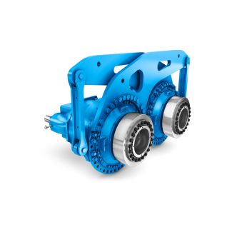
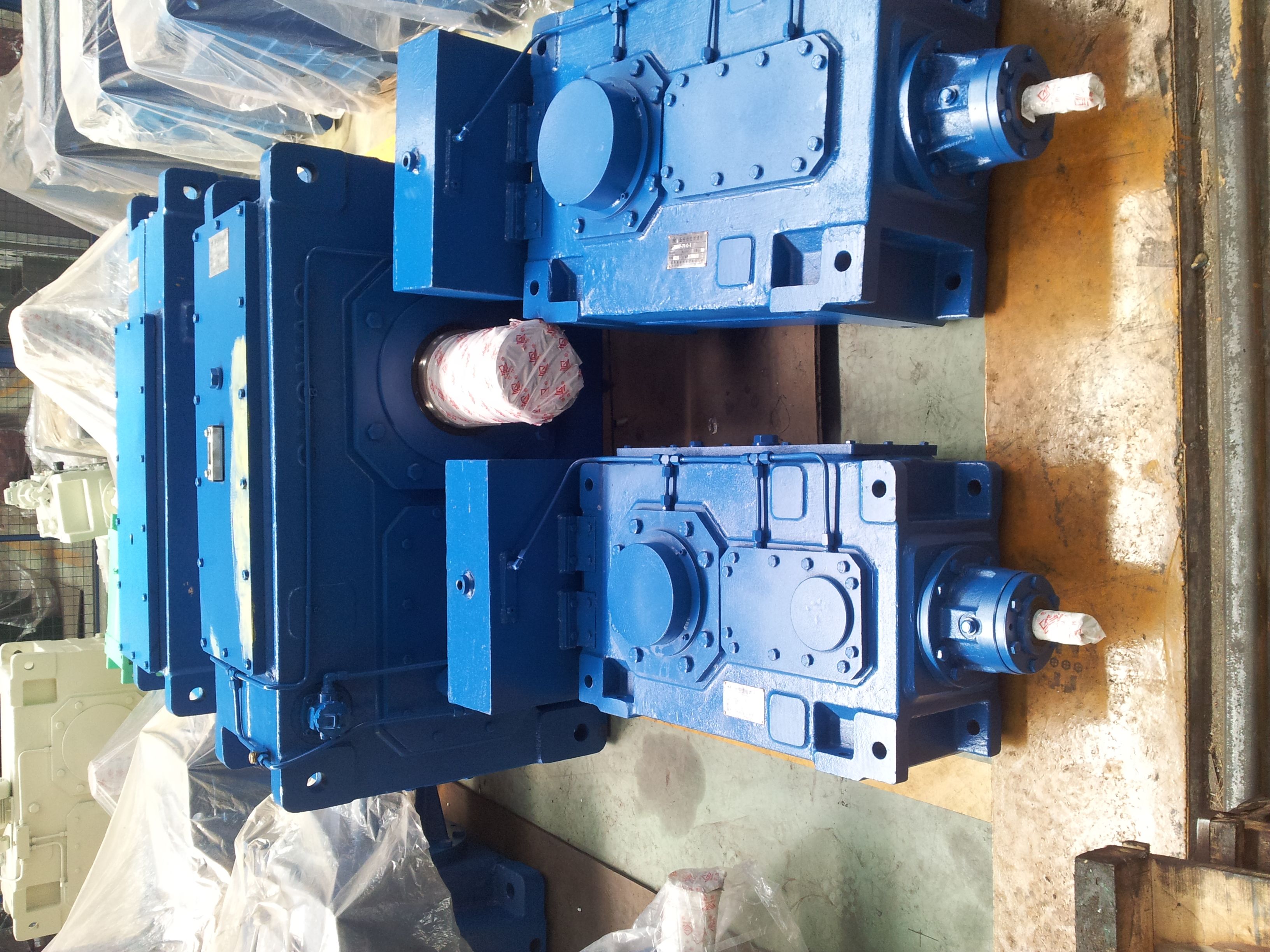
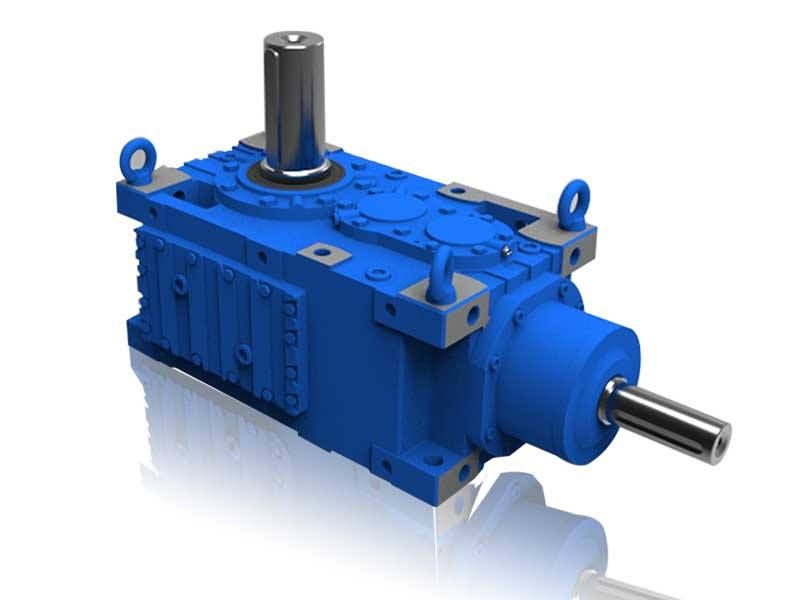
ct dimensions if applicable Max dimensions det B3-HH-7-A Bevel-helical gear reducers B3
In stock
SKU
B3-HH-7-A
$15,000.00
Flender/Flender Gear Units/Bevel-helical gear reducers B3
position of the Article No. Data position of Article No. 1 to 6 7 8 1"-" and order code Article No. 2LP2 -.....-....-... Design variant (view directed at face 2, face 1 at bottom) Type B2 to B3 to B4
  to A0 B1 C2 D3Irrespective of the spatial position of the gear unit, the face designations "right" and "left" always
  refer to the horizontal mounting position with the view directed at face 1. Face 2 is at the top. Assembly
  cover at top (, view directed at drive end face (: Face 3 = right Face 6 = left F5A G8 D8 G_MD3_XX_0 G_MD3_XX_0A G8D8 G_MD3_XX_0 3D8 G8 G8D8A G_MD3_XX_0 G8 D8 G_MD3_XX_0B G_MD3_XX_0 G8D8B G_MD3_XX_0 G8 G8D8 D8B G8D8 G_MD3_XX_0C G_MD3_XX_0 G8 D8C G_MD3_XX_0D8 G8 G8 D8C G_MD3_XX_0D G8D8 G_MD3_XX_0 G8 D8D G_MD3_DE_0 G8 G8D8 D8D G8 D8 G_MD3_XX_0E 1E G8D8 G_MD3_XX_0 3D8 G8 G8D8E G_MD3_XX_0 G_MD3_XX_0F G8D8 1F G8 D8 G_MD3_XX_0 D8 G8 G8D8F G_MD3_XX_0 $Backstop for types B2 and B3. Backstop not possible for: Type B2SL, designs , , , and type B2DL, designs and . %Backstop for type B4, gear unit sizes 5 to 5 &Backstop for type B4, gear unit sizes 5 to 5 Siemens AG 2 Bevel-helical gear units upright mounting position, output at bottom Types B2, B3 and B4 Article No. overview 9/1 Siemens MD 3.1 2Selection and ordering data (continued) 8th to 1th position of the Article No. Data position of Article No. 1 to 6 7 8 1"-" and order code Article No. 2LP2 .-..-....-... Output shaft, gear unit size Output shaft Gear unit size Solid shaft () 5 2A 5 3A 5 4A 5 5A 5 6A 5 7A 5 8A 5 0B 5 1B 5 2B 5 3B 5 4B Hollow shaft with keyway () 5 3D 5 4D 5 5D 5 6D 5 7D 5 8D 5 0E 5 1E 5 2E 5 3E 5 4E Hollow shaft for shrink disk () 5 3G 5 4G 5 5G 5 6G 5 7G 5 8G 5 0H 5 1H 5 2H 5 3H 5 4H Siemens AG 2 Bevel-helical gear units upright mo unting position, output at bottom Types B2, B3 and B4 Article No. overview 9/1 Siemens MD 3.1 2Selection and ordering data (continued) 8th to 1th position of the Article No. (continued) Data position of Article
| Model Type | Bevel-helical gear reducers B3 |
|---|---|
| Gear Type | Bevel Helical Gear |
| Weight (kg) | 700.000000 |
| Ratio Range | 1 : 12.5…71 |
| Low Speed Output | Hollow shaft with keyway acc. to DIN 6885/1 |
| Nominal Torque | 21700 Nm |
| Mounting Arrangements | Horizontal mounting position |
| Manufacturer | WALTHER FLENDER GMBH |
| Country of Manufacture | Jordan |
| Data Sheet & Drawings | ct dimensions if applicable Max dimensions det B3-HH-7-A Bevel-helical gear reducers B3 |
Related Products