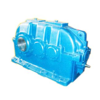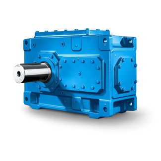
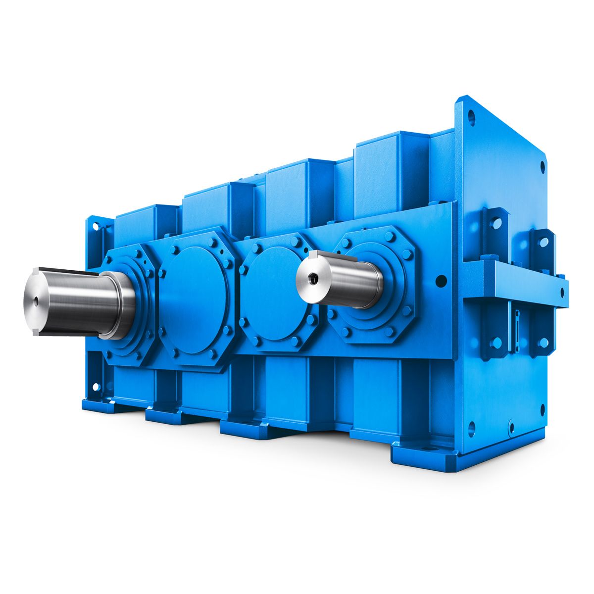

No LP Type Size d l G l kg Solid shaft w B3-DH-4-D Bevel-helical gear Reduction Boxes B3
In stock
SKU
B3-DH-4-D
$18,750.00
Flender/Flender Gear Units/Bevel-helical gear Reduction Boxes B3
radius of curvature in the lengthwise direction. Figure 3.2 shows the displacement behavior of the contact pattern on gear set cut with large tool radius. change in displaces the center of the contact pattern along the thick dashed line, change
  in along the thin dashed line. In simplied terms, it may be stated that displacement shifts the contact pattern along
  the face width, and displacement shifts it along the tooth depth. In drive mode, .. when <0 and >0, the
  center of the contact pattern migrates to the heel and, if there is bias-in, towards tooth tip,provided that and are equal in magnitude. Through suitable adjustments inV and , the contact pattern can reach almost any point on the tooth ank, provided sufcient backlash is available for the displacement. This property isuseful for the lapping operation as will be described in Sect. 6.6. Therefore, through and combinations, virtually any desired contact pattern position can be obtained and contact pattern correction can consequently be obtained by lapping in the displaced and positions. The above displacement behavior is detrimental in gearbox. The lever arm of the bending moment at the point of load application on the tooth of the wheelis larger, and an increase in tooth root stress in the heel zone is expected. Gearsdesigned in this way, without pre-corrected position for the contact pattern,often show tendency for the wheel tooth to break at the heel as result ofexcessive tooth root stress. To obtain tooth with the necessary load capacity, it is desirable to have displacement of the contact pattern which is insensitive to the typical combination of and , combined to the largest possible normal module. The relationships in Table 3.7are valid for the basic crown gear shown in Fig.3.2, with number of teeth , spiral angle xat cone distance Rxand distance P0(crown gear center to cutter center). Table 3.7 Relationships for Fig. 3.2 expressed in the form of equations Designation Formula No.
| Model Type | Bevel-helical gear Reduction Boxes B3 |
|---|---|
| Gear Type | Bevel Helical Gear |
| Weight (kg) | 875.000000 |
| Ratio Range | 1 : 12.5…71 |
| Low Speed Output | Hollow shaft with shrink disk |
| Nominal Torque | 6700 Nm |
| Mounting Arrangements | Horizontal mounting position |
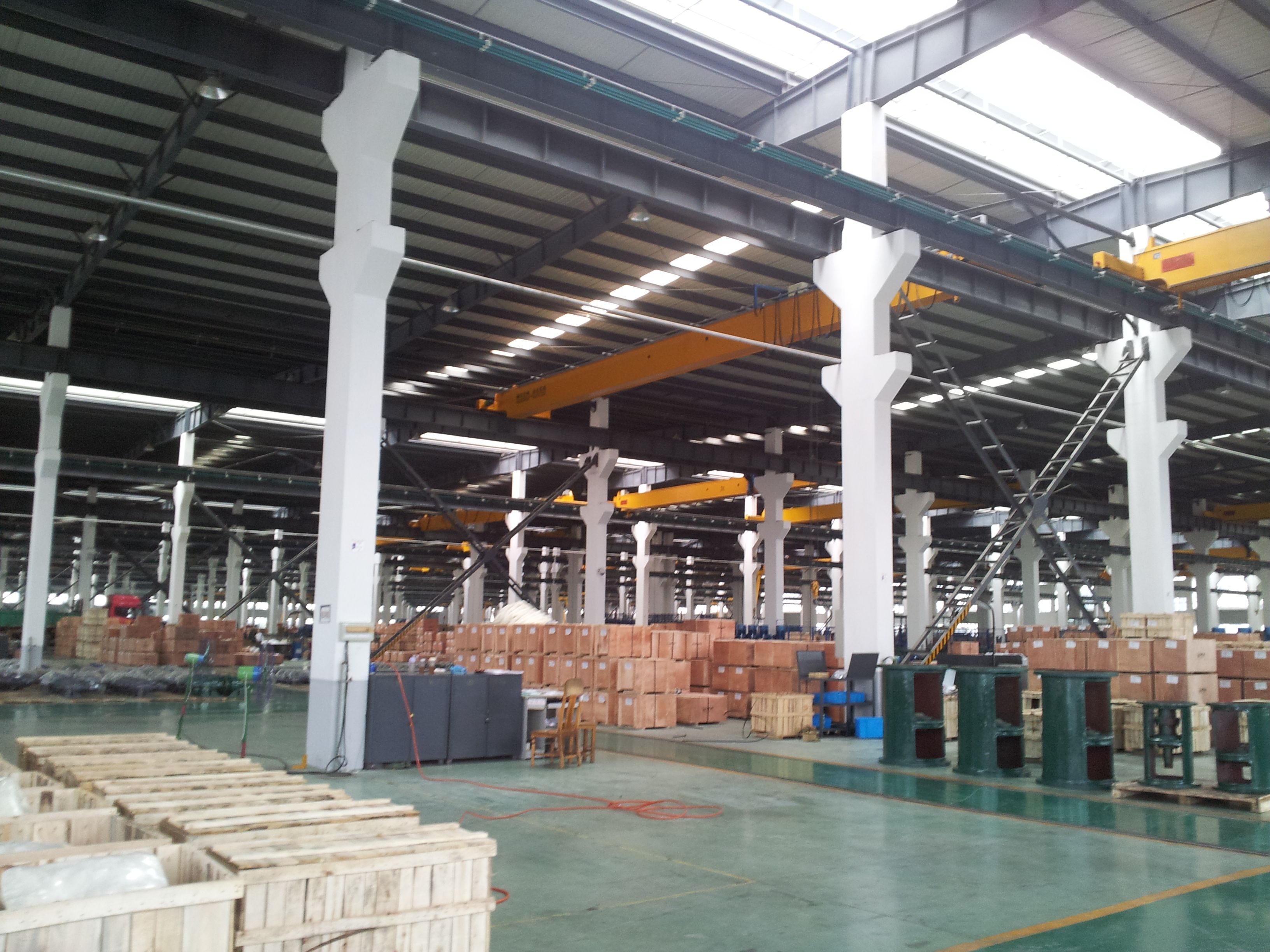
| Manufacturer | Siemens AG |
| Country of Manufacture | Oman |
| Data Sheet & Drawings | No LP Type Size d l G l kg Solid shaft w B3-DH-4-D Bevel-helical gear Reduction Boxes B3 |
Related Products