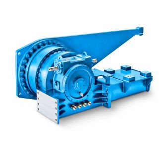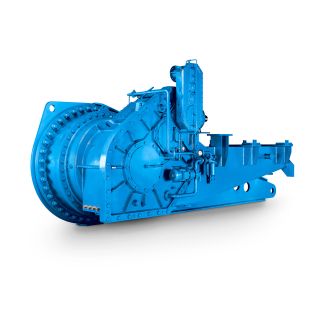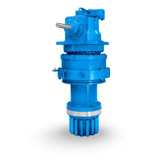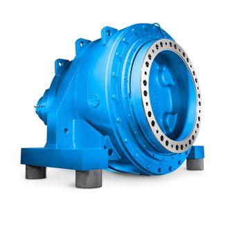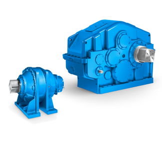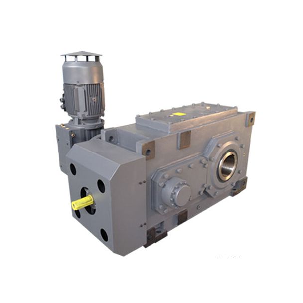
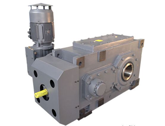
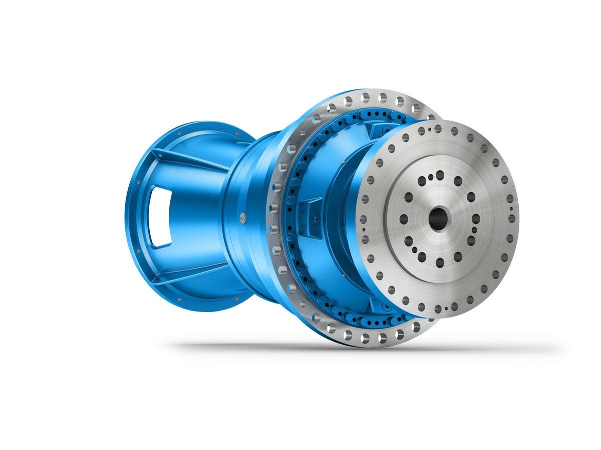
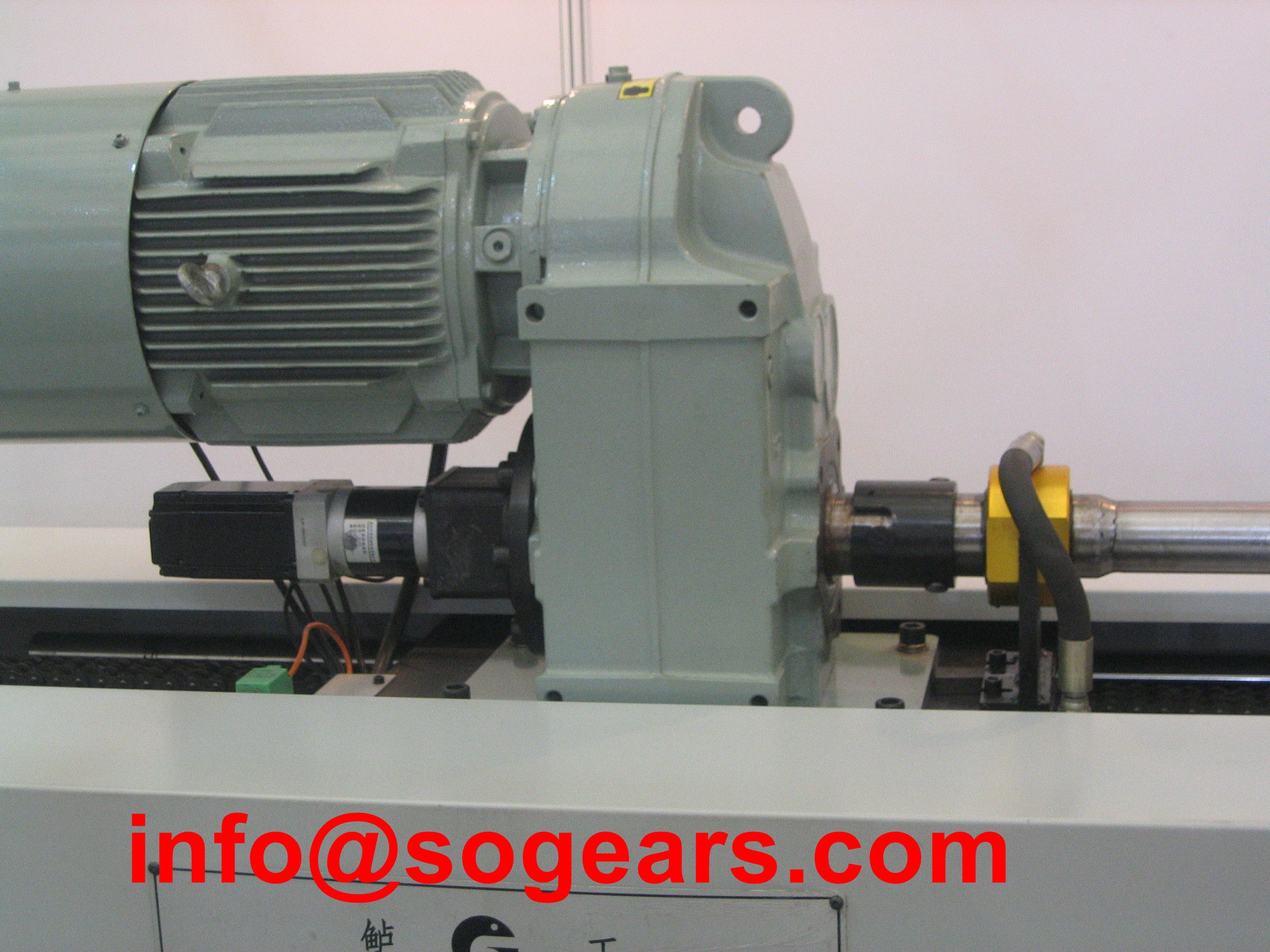
B3-CV-7-A GMDENLSS External flangemounted pumps p m bc m an Bevel-helical speed reducer B3
In stock
SKU
B3-CV-7-A
$15,000.00
Flender/Flender Gear Units/Bevel-helical speed reducer B3
parts shall also be furnished for verification during inspection. 1.3 For heavy valves, provision for lifting shal be made by way of lugs, eyebolts, or similar standard devices. 1.4 Unless otherwise stated, all flanged valves shall have end flange integral
  with valve body. Weld on flanges are not acceptable. Fl ange finish shall be serrated finish 2 AARH (2 AARH
  to 5 AARH) or 1 AARH (1 AARH to 2 AARH) or 6 MRH (3 AARH to 6 AARH) as
  per valve specification sheet. 1.5 For all weld end valves, with bevel end as per ANSI 1.2, the bevel contour shall be as follows: Material Wall Thickness Weld Contour Carbon Steel (Except Low Temp. Carbon Steel) Upto 2 mm > 2 mm Figure 2 Type Figure 3 Type Alloy Steel Upto 1 mm Figure 4 Stainless Steel & Low Temp Carbon Steel > 1 mm & upto 2 mm > 2mm Figure 5 Type Figure 6 Type 1.6 If an overlay weld-deposit is used for the body seat ring, seating surface, the seat ring base material shall be at least equal to the corrosion resistance of the materials of the shell. 1.7 For valve body/ bonnet, forging is acceptab le where castings are specified but not vice versa. 1.8 Material of construction of yoke shall be as minimum equivalent to body/ bonnet material. 1.9 Stem shall be forged or machined from forged bar. Castings are not permitted except integral stem. 1.1 Stelliting/ hard facing by deposition shall have minimum 1.6mm thickness. Renewable seat rings shall be seal welded. 1.1 Face to face dimension of flanged valves shall conform to ANSI 1.1 to the extent covered. For valves not covered in the ANSI specification, Contractor shall furnish certified dimensional drawings. 9 of 1 1.1 Flange dimensions of steel, alloy steel and stainless steel flanged valves shall conform to ANSI 1.5 for sizes up to 2 and API 6 for size 2 and above. 1.1 Flange dimensions for cast iron flanged valves shall conform to ANSI 1.1 for size up to 2 class 1 and API 6 with flat face for
| Model Type | Bevel-helical speed reducer B3 |
|---|---|
| Gear Type | Bevel Helical Gear |
| Weight (kg) | 700.000000 |
| Ratio Range | 1 : 12.5…71 |
| Low Speed Output | Solid shaft without parallel key |
| Nominal Torque | 21700 Nm |
| Mounting Arrangements | Vertical mounting position |
| Manufacturer | Flender (Australia) Pty. Ltd. |
| Country of Manufacture | South Korea |
| Data Sheet & Drawings | B3-CV-7-A GMDENLSS External flangemounted pumps p m bc m an Bevel-helical speed reducer B3 |
Related Products