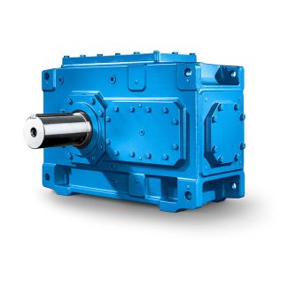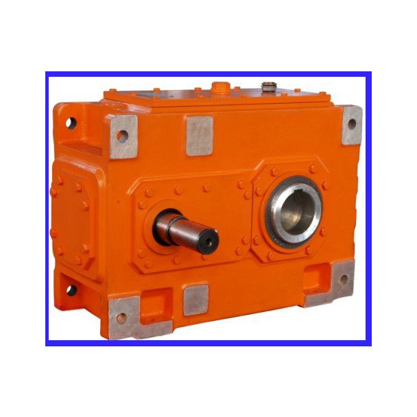
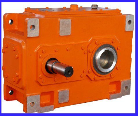


this P Pn is the operating cycle in the time B2-SV12A Bevel-helical gearboxes B2
In stock
SKU
B2-SV12A
$546,428.57
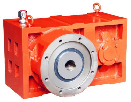
Flender/Flender Gear Units/Bevel-helical gearboxes B2
listed in Table 3.4determine the gear blank as described in Sect. 2.3.Table 3.3 Motion equations of the virtual machine expressed as Taylor series Designation Formula No. Radial motion abm m 2...m 6 (3. Vertical motion abm m 2...m 6 (3.
  Angular motion abm m 2...m 6 (3. Horizontal motion abm m 2...m 6 (3. Helical motion abm m 2...m 6
  (3. Modied roll ; cabm m 2...m 6(3.7 3 Design Figure 3.9shows the relative position of the bevel gear and
  the tool. The settings of the virtual machine can be derived from the formulae given in Table 3.5.Table 3.4 Macro geometry of bevel gearVariable Symbol Number of teeth Mean cone distance Rm Pitch angle Addendum ha Dedendum hf Prole shift xhmmmn Hypoid offset in the pitch plane ap Mean spiral angle Tool radius in the pitch plane rc0 Fig. 3.9 Relative positions of the bevel gear and tool3.2 Manufacturing Kinematics 7 3.3 Tooth Contact Analysis 3.3.1 Tooth Geometry Calculation Tooth contact analysis is an important tool for the design, evaluation and optimi- zation of bevel gears. It also forms the basis for more exact stress calculation methods. To conduct load-free tooth contact analysis, the tooth anks are meshed by calculation in load-free process. During meshing, it is possible to calculate theease-off (see Sect. 3.3.3 ), the transmission error and the contact pattern. In order to simulate tooth contact and calculate local loads and stresses, it is necessary to know the tooth ank and tooth root geometry including the transitionbetween tooth ank and tooth root. It is also necessary to know the spatial positionof the pinion and wheel. Tooth contact analysis can be done from the calculatedgeometry or from coordinates obtained with three-dimensional gear measurement machine. Since tooth ank and tooth root geometry depends on the manufacturing method, as noted in Sect. 2.1, to calculate the tooth coordinates, it is necessary to simulate the gear m
| Model Type | Bevel-helical gearboxes B2 |
|---|---|
| Gear Type | Bevel Helical Gear |
| Weight (kg) | 25500.000000 |
| Ratio Range | 1 : 6.3…22.4 |
| Low Speed Output | Solid shaft with parallel key acc. to DIN 6885/1 |
| Nominal Torque | 66300 Nm |
| Mounting Arrangements | Vertical mounting position |
| Manufacturer | Flender Macneill Gears Ltd. |
| Country of Manufacture | Armenia |
| Data Sheet & Drawings | this P Pn is the operating cycle in the time B2-SV12A Bevel-helical gearboxes B2 |
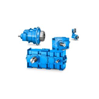
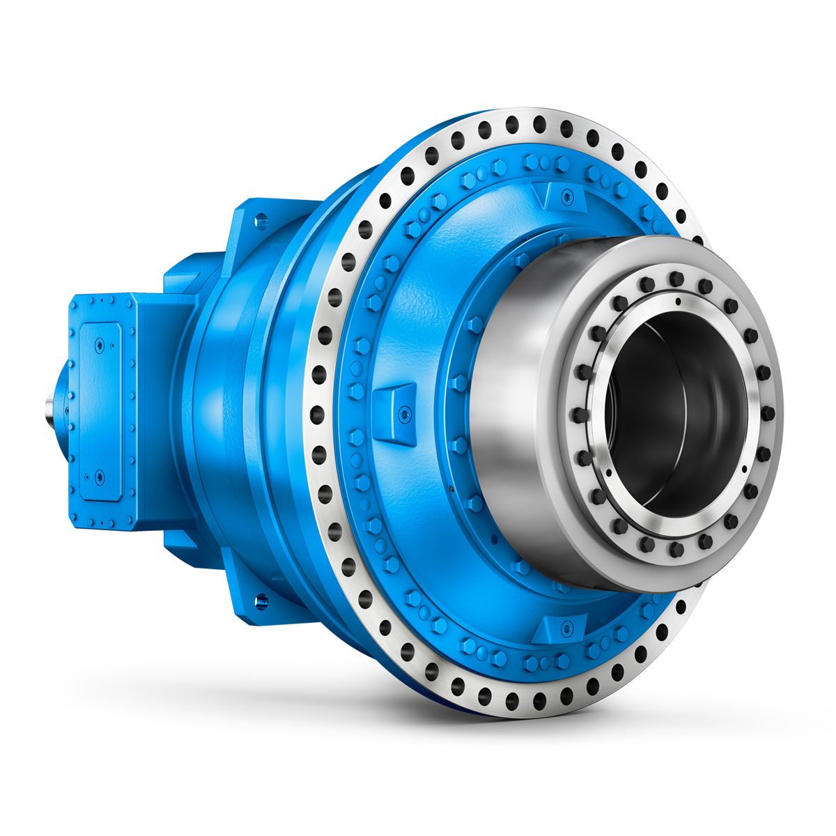
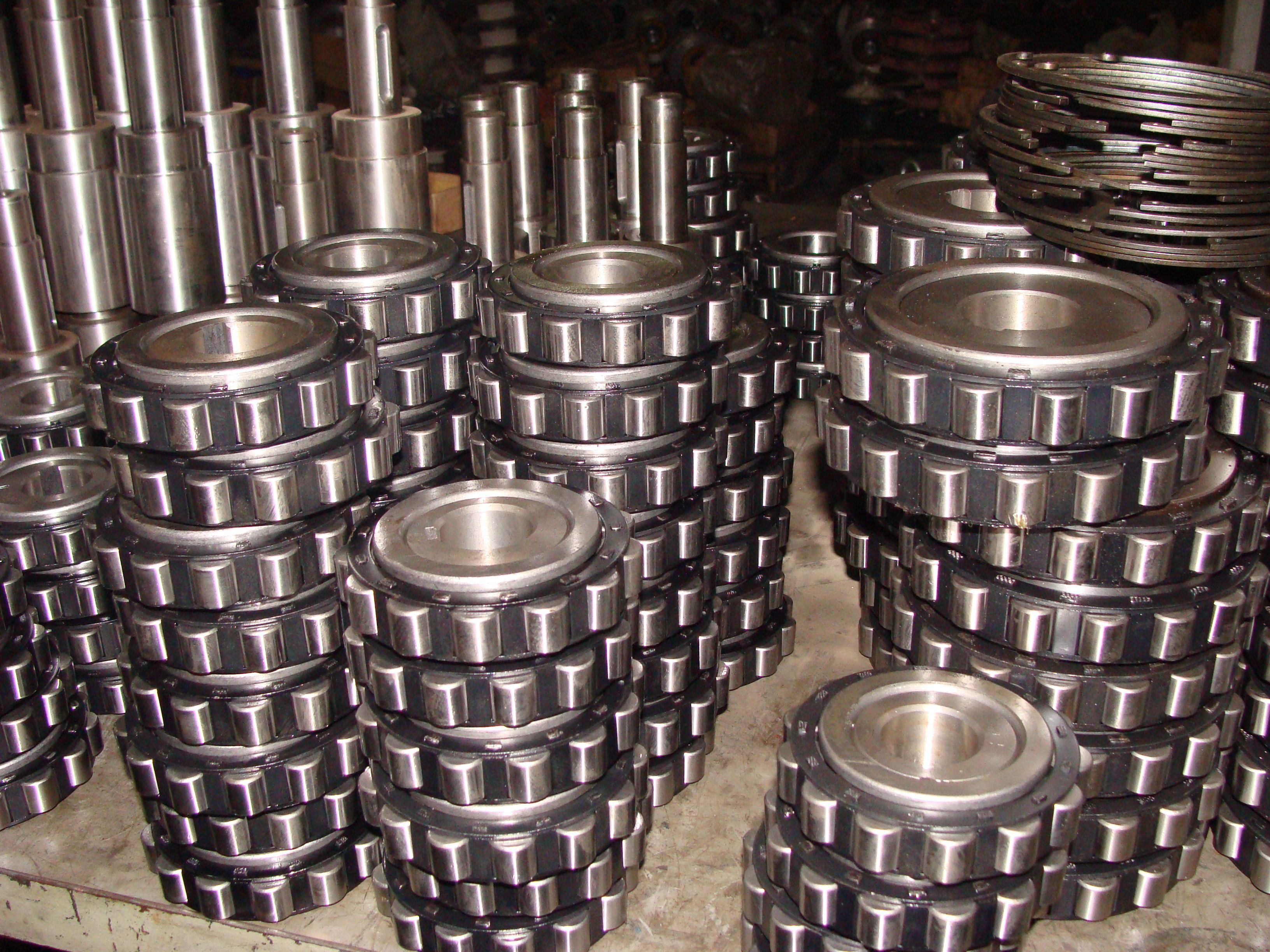
Related Products