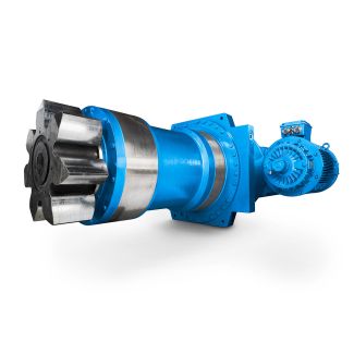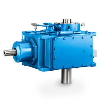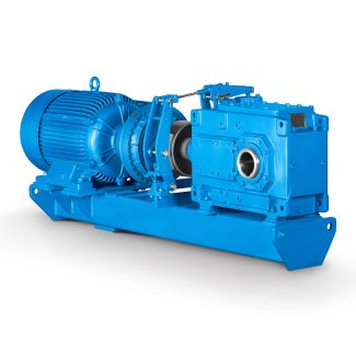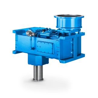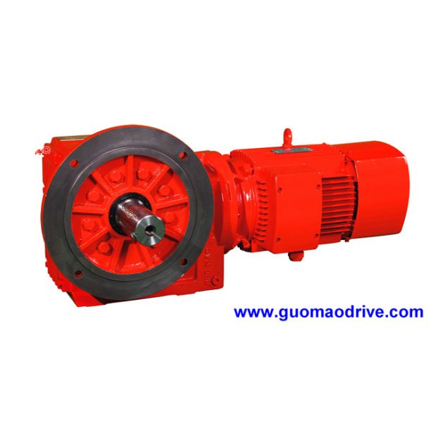
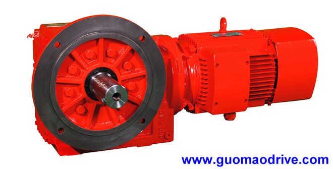
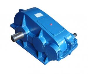
B2-SH-6-D sity nonuniform gas absorption Toasters C Bevel-helical speed reducers B2
In stock
SKU
B2-SH-6-D
$11,571.43
Flender/Flender Gear Units/Bevel-helical speed reducers B2
le 4.2 Geometry of virtual cylindrical gears in the transverse section acc. to [ FVA4 ] Designation Formula No. Pitch diameterdv1,2dm1,2 cos1,2de1,2 cos1,2Rm Re(4. for a0m and9/C1:dv1dm1 u2p ;dv2dv1u2(4. Center distance avdv1dv2 =2 (4. Tip diameter dva1,2dv1,2ham1,2 (4. Root diameter
  dvf1,2dv1,2hfm1,2 (4. Helix angle vm1m2 =2 (4. Base helix angle vbarcsin sin vcosn (4. Base diameter dvb1,2dv1,2cosvet (4. where: vetarctantane
  cosv/C1/C1 eeDacc. to [ ISO2 ] on the drive ank eeCacc. to [ ISO2 ] on the coast ank(4. Transverse
  modulemvtmmn=cosv (4. Number of teeth zv1,2dv1,2=mvt (4. Gear ratio for a0m and9/C1uvzv2=zv1 (4. uvz2 z1/C1/C1 u2(4. Number of teeth for a0m and9/C1:zv1z1 u2p (4. zv2z2 u2p(4. Base pitchpvetmmn/C1/C1cosvet cosv(4.1 4 Load Capacity and Efciency Length of the line of contactgv1 dva1dvb1/C1q dva2dvb2/C1q /C2/C2 avsinvet(4. Face widthbvb2bveff b2eff(4. where: bveffb2eff cos mP=2gvcosvetsinmP=2/C1/C1 1tan0sinmP=2 b2effeffective contact pattern width on the wheel for specic load. The width of the contact pattern is estimated, measured, or calculated using loaded tooth contact analysis software (see Sect. 4..(4. mParctan sin 2tanm (4. 0mPmP=2 mPoffset angle in the crown gear plane moffset angle in axial plane according to [ ISO2 ](4. Prole contact ratiovgv pvet(4. Overlap ratiovbveffsinv mmn(4. Total contact ratiovvv (4. Equivalent cur- vature radiuserst/C1cos2wBel where: wBelangle between the contact line and pitch cone in the ank tangential plane tequivalent radius of curvature in the prole section tcosm1cosm2 cosntanntanlim tanmPtanwBel /C1 cosmP/C1 Rm2tan2 Rm1tan1/C1/C1 /C2 /C2(4. (4. (continued)4.2 Load Capacity Calculation 1 Table 4.2 (continued) Designation Formula No. where: nnDacc. to [ ISO2 ] on the drive side ank nCacc. to [ ISO2 ] on the coast side ank wBelarctan tan vsine (4. where: eeDacc. to [ ISO2 ] on the drive side ank eeCacc. to[ ISO2
| Model Type | Bevel-helical speed reducers B2 |
|---|---|
| Gear Type | Bevel Helical Gear |
| Weight (kg) | 540.000000 |
| Ratio Range | 1 : 6.3…22.4 |
| Low Speed Output | Solid shaft with parallel key acc. to DIN 6885/1 |
| Nominal Torque | 12000 Nm |
| Mounting Arrangements | Horizontal mounting position |
| Manufacturer | FLENDER ZAHNRADGETRIEBE |
| Country of Manufacture | Marshall Islands |
| Data Sheet & Drawings | B2-SH-6-D sity nonuniform gas absorption Toasters C Bevel-helical speed reducers B2 |
Related Products