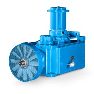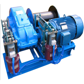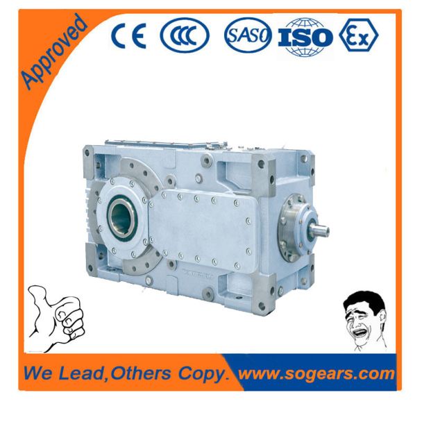

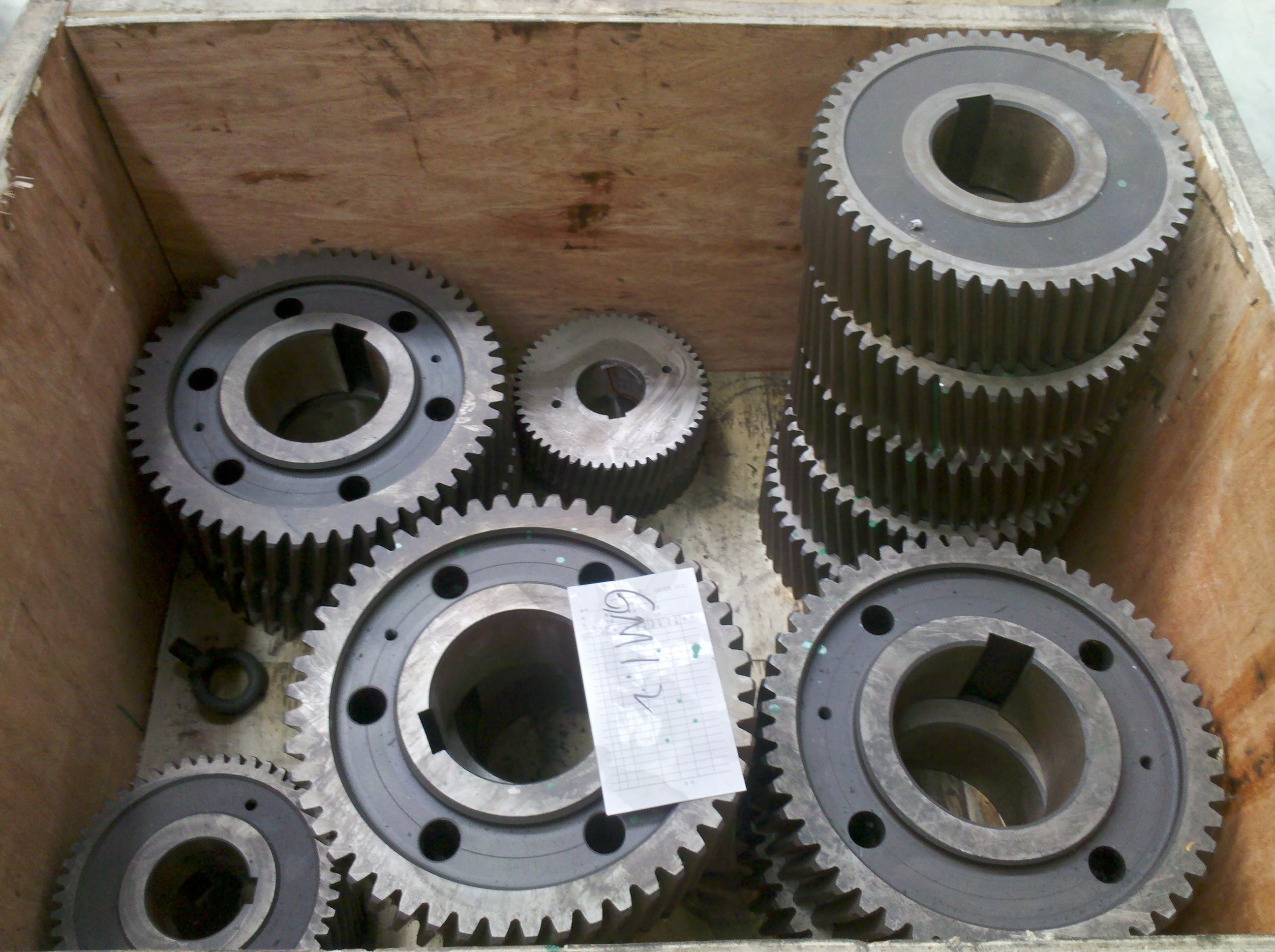
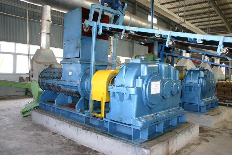
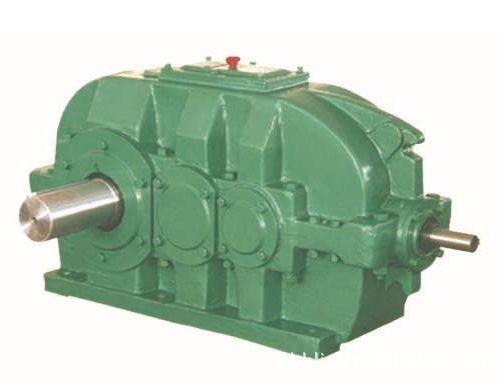
H4DV-15-C colorhighlighted are provided for the gear unit Helical gear unit H4
In stock
SKU
H4DV-15-C
$30,000.00
Flender/Flender Gear Units/Helical gear unit H4
indicate whether separately excited or self-excited vibrationspredominate in the process under investigation. The spectral composition of thevibrations which occur during the cutting operation is analyzed for this purpose. In the case of separately excited vibrations, the machine tool vibrates at
  tool mesh frequency or one of its harmonics, while the spectrum for self-excitedvibrations primarily reveals vibration components close to machine
  resonant frequency. In practice, an important distinction is that, in the case of self-excited vibrations, only slight changes in the
  frequency of the machine vibrations appear8.3 Dynamic Machine Behavior 3 when the process excitation frequency is alteredfor example by varying the rotation speed of milling cutterwhile in the case of separately excited vibrations the dominant machine frequency changes in proportion to the speed of rotation. With separately excited vibrations, changing the tool rotational frequency is often enough to stabilize the process. simulation at the design phase can determine the frequency and amplitude of machine vibrations before new machine is built. Subsequent testing of dynamic machine behavior, in the form of compliance frequency responses, can be used to improve modeling for future designs. For example, an actuator can be used to apply an alternating force to the machine structure. Absolute or relative actuators can be used. They are located between the tool and work piece with static pre-load to simulate the static cutting force component in the process and eliminate the inuence of clearances on measurement results (Fig. 8.. At the same time, the relative displacement is captured by an inductive displace- ment transducer and the acceleration signals of both the work piece and the tool are measured by accelerometers. The sensors and the actuator are often attached separately to the tool and to the work piece. The measuring set-up, which is repeated for each of the three orthog- onal directions
| Model Type | Helical gear unit H4 |
|---|---|
| Gear Type | Helical Gear |
| Weight (kg) | 1400.000000 |
| Ratio Range | 1 : 100…355 |
| Low Speed Output | Hollow shaft with shrink disk |
| Nominal Torque | 153000 Nm |
| Mounting Arrangements | Vertical mounting position |
| Manufacturer | WALTHER FLENDER GMBH |
| Country of Manufacture | China |
| Data Sheet & Drawings | H4DV-15-C colorhighlighted are provided for the gear unit Helical gear unit H4 |
Related Products