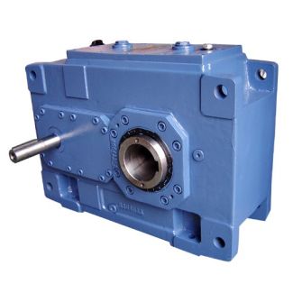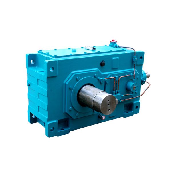
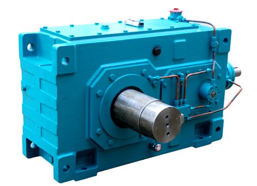


H4-VV-25-A fluid couplings allow the torquelimited approach Helical gear unit H4
In stock
SKU
H4-VV-25-A
$195,000.00
Flender/Flender Gear Units/Helical gear unit H4
geometries which cannot be realized in cuttingoperations. Apart from these advantages, the chief drawbacks of forging processTable 6.1 Bevel gear manufacturing processesNon-cutting processes Cutting processes Casting Planing Sintering Milling Extrusion Hard skivingDie forging GrindingTumble forging Lapping Honing Springer-Verlag Berlin Heidelberg
  2 . Klingelnberg (ed.), Bevel Gear , DOI 1.1/9-3-6-4-0_6 are the high cost of dies and the complex process design.
  Any modication of the gear, for example contact pattern corrections, which in cutting process can be realized by changing the
  machine settings, will demand new and costly die. Cutting Processes This topic applies solely to planing (shaping) and milling of straight and skew bevel gears. Production processes for spiral bevel gears are described in Sects. 6.2,6.4and6.5. In the past, the planing of straight or skew bevel gears was widely used. The best known method in Germany was developed by Heidenreich-Harbeck [ DEGN0 ] and has in the meantime been replaced by more productive methods. It is now used to only limited extent in single and spare part production. Straight Bevel Gear Milling The operations currently used to produce straight bevel gears are milling and broaching. Three methods, distinguished only by the tools employed, are used for milling with generating motion. These are known as Coniex(Gleason), Konvoid (Modul) and Sferoid (Klingelnberg). Typical for all three methods are: tooth shape: tapered depth manufacturing: single-indexing method; both pinion and wheel are generated tool: two intermeshing cutters with radial blades prole crowning: by machine kinematics lengthwise crowning: curved blade paths The axes of two disc-shaped cutters, one for the left tooth ank, one for the right tooth ank, are at an angle to each other, causing the blades to intermesh alternately in such way that their primary cutting edges form trapezoidal prole. Since the cutting edges do not lie precisely in the plane of r
| Model Type | Helical gear unit H4 |
|---|---|
| Gear Type | Helical Gear |
| Weight (kg) | 9100.000000 |
| Ratio Range | 1 : 100…355 |
| Low Speed Output | Solid shaft with parallel key acc. to DIN 6885/1 with reinforced spigot |
| Nominal Torque | 860000 Nm |
| Mounting Arrangements | Vertical mounting position |
| Manufacturer | FLENDER TÜBINGEN GMBH |
| Country of Manufacture | Australia |
| Data Sheet & Drawings | H4-VV-25-A fluid couplings allow the torquelimited approach Helical gear unit H4 |
Related Products