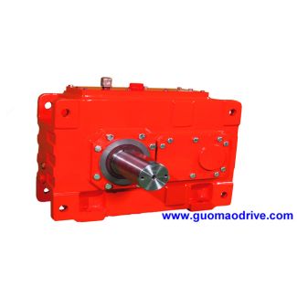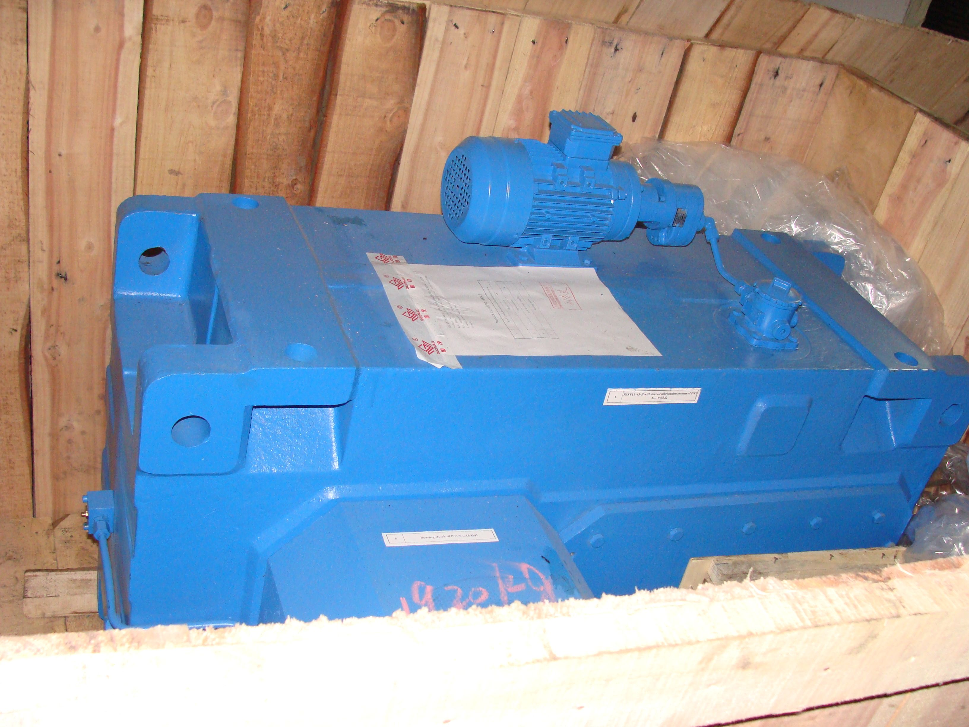

H4-VV-17-D Nm Nm TypeSize B B B B B B B B B B B Ratio range Helical gear Reduction Boxes H4
In stock
SKU
H4-VV-17-D
$49,178.57
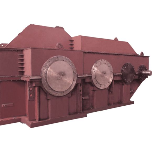
Flender/Flender Gear Units/Helical gear Reduction Boxes H4
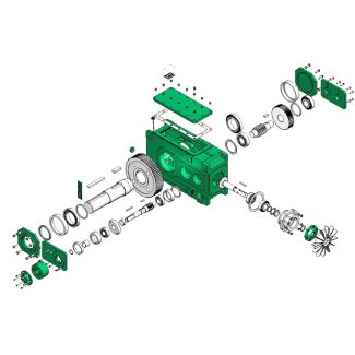
gear pulling it towards the crossing point and hence into engagement (see Fig. 2.2.5 Tooth Forces 5 2.5.3 Bearing Forces Forces acting on bearing may be calculated from tooth forces and additional external forces. The radial force on the bearings
  thus contains components of the tangential, axial and radial forces of the gear mesh and additional external force components. The
  axial force on the bearing is the axial tooth force plus external force components. References [AGMA2] ANSI/AGMA 2-D0: Design Manual
  for Bevel Gears ( [COLE5] Coleman, .: Improved method for estimating fatigue life of bevel and hypoid gears. SAE . Trans. 6(2S), 3 ( [ISO2] ISO 2: Bevel and Hypoid Gear Geometry ( [KN3] Auslegung von Hypoid-Getrieben mit Klingelnberg Zyklo-Palloid-Verzahnung: Klingelnberg GmbH ( [NIEM8.3] Niemann, ., Winter, .: Maschinenelemente Band III. Springer, New York ( [SEIB0] Seibicke, .: Dimensionierung, Auslegung und Herstellung von Kegelradsa tzen mit inverser Spirale; Dresdner Maschinenelemente Kolloquium 2, Tagungsband; Verlagsgruppe Mainz GmbH ( Fig. 2.2 Tooth forces. 1 pinion, 2 wheel, 3 direction of rotation5 2 Fundamentals of Bevel Gears Chapter 3 Design 3.1 Starting Values for the Geometry Apart from high functional reliability, modern bevel gear sets are subjected to considerable demands in terms of transmitted torque, small mass, low production costs and low noise. The most important starting values inuencing the basic geometrical design of bevel gears are: the transmission ratio the shaft angle the hypoid offset the transmitted torque the installation space and hence the outside diameter e2of the wheel Torque and required installation space naturally inuence each other as, depending on the design (geometry and material), particular gear size will onlybe able to transmit specic maximum torque. The variables describing the basic geometry are interrelated in manner appar- ent from the following equation. e2b2/C1sin2u/C1z1/C1mmn cosm2:1
| Model Type | Helical gear Reduction Boxes H4 |
|---|---|
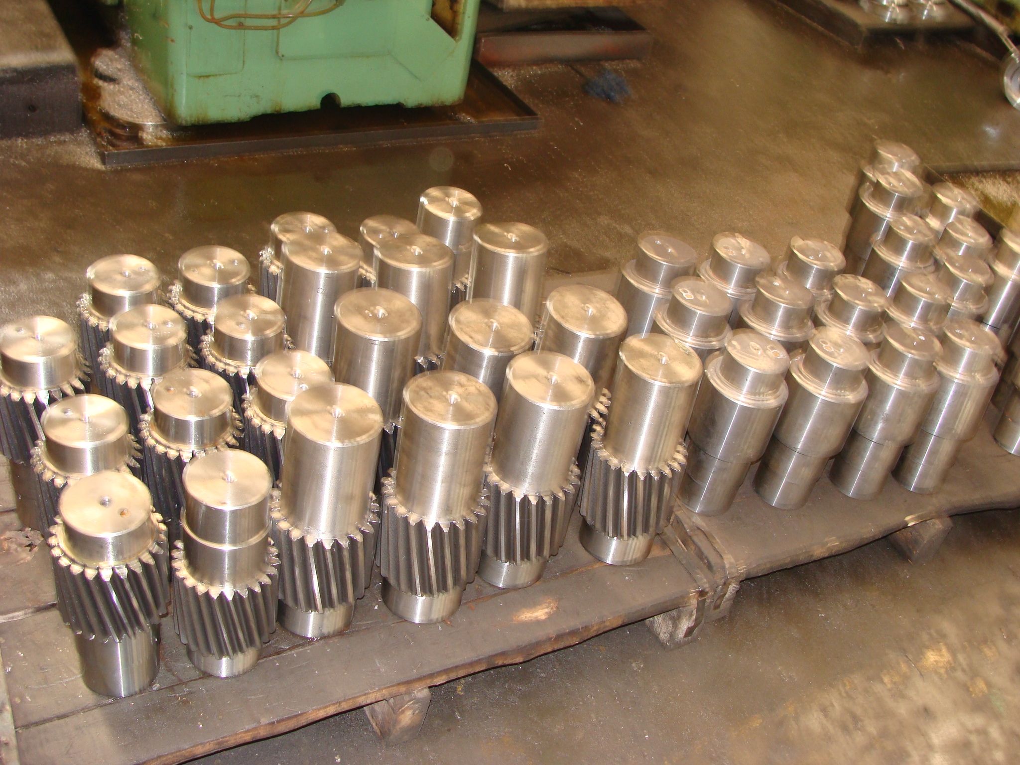
| Gear Type | Helical Gear |
| Weight (kg) | 2295.000000 |
| Ratio Range | 1 : 100…355 |
| Low Speed Output | Solid shaft with parallel key acc. to DIN 6885/1 with reinforced spigot |
| Nominal Torque | 200000 Nm |
| Mounting Arrangements | Vertical mounting position |
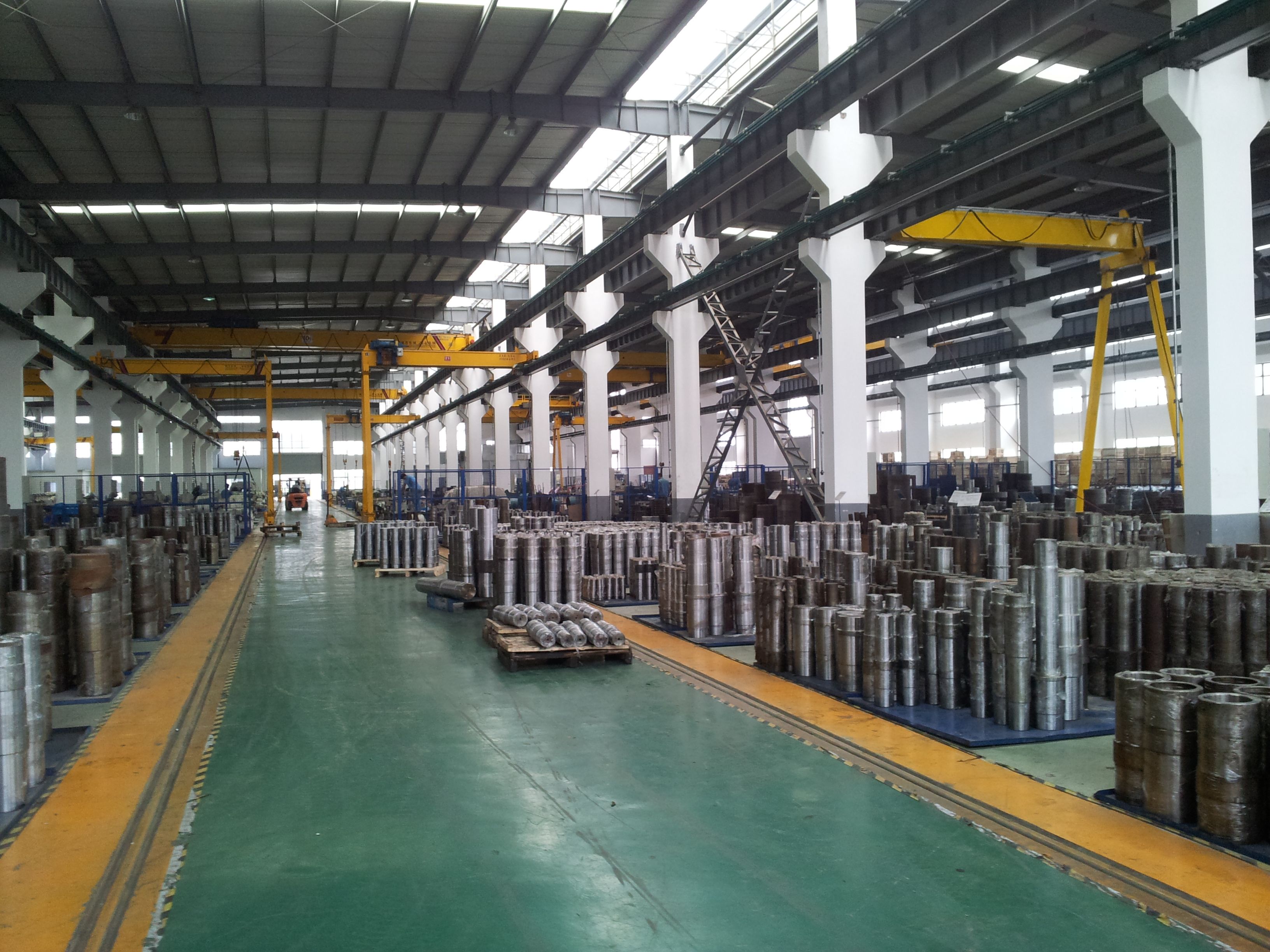
| Manufacturer | Flender de Mexico, S.A. de C.V. |
| Country of Manufacture | China |
| Data Sheet & Drawings | H4-VV-17-D Nm Nm TypeSize B B B B B B B B B B B Ratio range Helical gear Reduction Boxes H4 |
Related Products