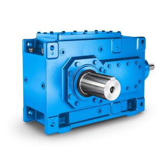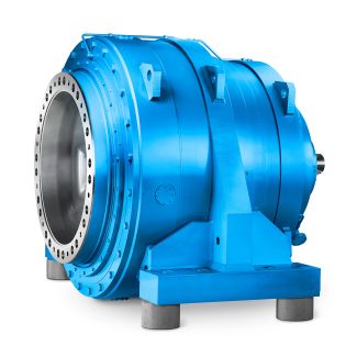
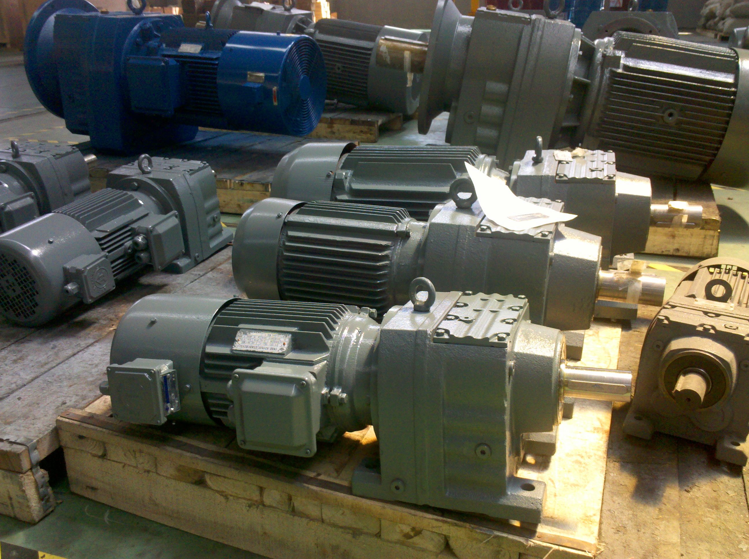
Helical gear box H4 GmbH Flender MD Design of the gear units Gui H4-FV26A
In stock
SKU
H4-FV26A
$210,000.00
Flender/Flender Gear Units/Helical gear box H4
lated according to Table 4.6, considering the hypoid-specic property of differently oriented tangential velocities F1and F2on the tooth anks.Table 4.5 Calculation of scufng safety factor int Designation Formula No. Scufng safety factorSintSintS int>SSmin(4. SSIwBtmax wBt eff/C2intSoil intoil(4. Minimum safetyfactorsS Smin<1
  high risk of scufng 1/C2SSmin/C2 scufng risk dependent on exact knowledge of tooth ank roughness, run-in state, overloads, etc. SSmin>2
  low scufng riskTable 4.5 Calculation of the permissible integral temperature intS Designation Formula No. Permissible integral temperature intSMTC2XwrelTfl aintT (4.
  where: C2.5 MT8:2/C1T1T/C1XL (4. fl aintT0:2/C1T1T/C1 4/C1/C1:0 /C1XL(4. T1T3:7/C1SFZG2 XLaccording to Table 4.4(4.1 4 Load Capacity and Efciency Tooth ank tangential velocities F1,2 In calculating the ash temperature for hypoid gears, it is necessary to consider the local tooth ank tangential veloc- ities F1,2and the associated angle relative to the contact line 1,2of the virtual crossed-axes helical gears. These values can be determined using the calculation method according to [ WECH8 ]. The circumferential speeds of the pinion and wheel, t1and t2, at the relevant contact point are projected on the tooth ank tangential plane (component ) and on the plane of action (component ) (Fig. 4.. Components and are again divided into their components perpendicular to (,) and parallel to ( ,) the tooth trace. The tooth ank tangential velocities vF1,2for the pinion and wheel are then obtained by vector addition (Fig. 4.2 and Table 4.. Fig. 4.2 Projection of the circumferential speed tat the relevant contact point on the tooth ank tangential plane and the plane of action ETable 4.6 Calculation of the ash temperature for hypoid gears Designation Formula No. Flash temperaturefl1:1/C1m/C1XJ/C1X/C1wBn/C1vF1vF2 jj 2bH1=2/C1BM1/C1vF1sin1 1=2BM2/C1vF2sin2 1=2(4. mmean coefcient of friction according to Table 4.4 XJmesh approa
| Model Type | Helical gear box H4 |
|---|---|
| Gear Type | Helical Gear |
| Weight (kg) | 9800.000000 |
| Ratio Range | 1 : 112…400 |
| Low Speed Output | Flanged shaft |
| Nominal Torque | 1030000 Nm |
| Mounting Arrangements | Vertical mounting position |
| Manufacturer | Flender Svenska AB |
| Country of Manufacture | Iraq |
| Data Sheet & Drawings | Helical gear box H4 GmbH Flender MD Design of the gear units Gui H4-FV26A |
Related Products