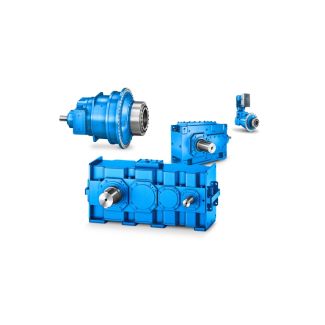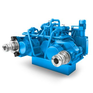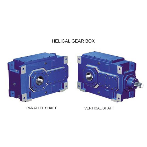
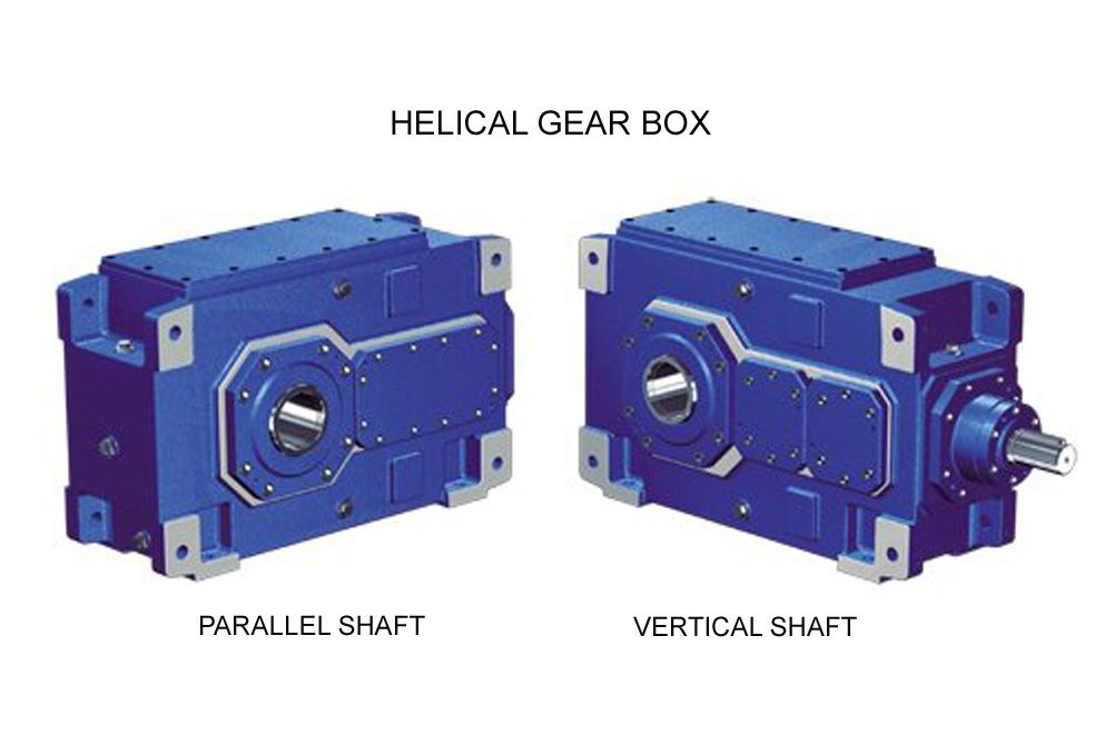
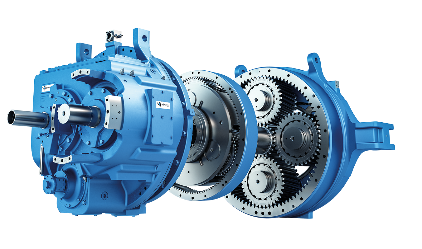
Helical speed reducer H4 ntinued Thermal factor Kth Note The listed load p H4FV-26-C
In stock
SKU
H4FV-26-C
$210,000.00
Flender/Flender Gear Units/Helical speed reducer H4
lateral deflection. The Contractor shall maintain parallelism of restraining rings or bellows convolutions. Precautions xFor carrying out welding, earthing lead shall not be attached ith the Expansion Joint. xThe Expansion bellow shall be protected from arc weld spot and welding
  spatter. xHydrostatic Testing of the system having Expansion Joint shall be performed with shipping lugs in position. These lugs shall
  be removed after te sting and certification is over. 5.6 Flange Connections While fitting up mating flanges, care shall be
  exercised to pro perly align the pipes and to check the flanges for trueness, so that faces of the flanges can be ulled together, without inducing any stresses in the pipes and the equipment nozzles. Extra care connections to pumps, turbines, compressors, cold boxes, air co olers etc. The flange connections to these equipments shall be checked for misalignment, excessive gap etc. after the final alignment of the equipment is over. The joint shall be made up after obtaining approval of Engineer-in-Charge. Temporary protective covers shall be retained on all flange con nections of pumps, turbines, compressors and other similar equipments, until the piping is inally connected, so as to avoid any foreign material from entering these equipments. The assembly of flange joint shall be done in such way that the gasket between these flange faces is uniformly compressed. To achieve this the bolts shall be tightened in proper sequence. All bolts shall extend completely through their nuts but not more than 1/4". Steel to .. flange joints shall be made up with extreme care, tightening the bolts uniformly after bringing flange flush with gaskets with accurate pattern and lateral alignment. 5.7 Vents and Drains High point vents and low point drains shall be provided as per the instructions of Engineer-in- Charge, even if these are not shown in the drawings. The details of vents and drains sha
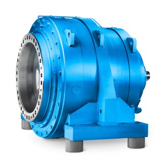
| Model Type | Helical speed reducer H4 |
|---|---|
| Gear Type | Helical Gear |
| Weight (kg) | 9800.000000 |
| Ratio Range | 1 : 112…400 |
| Low Speed Output | Flanged shaft |
| Nominal Torque | 1030000 Nm |
| Mounting Arrangements | Vertical mounting position |
| Manufacturer | Flender Brasil Ltda |
| Country of Manufacture | Germany |
| Data Sheet & Drawings | Helical speed reducer H4 ntinued Thermal factor Kth Note The listed load p H4FV-26-C |
Related Products