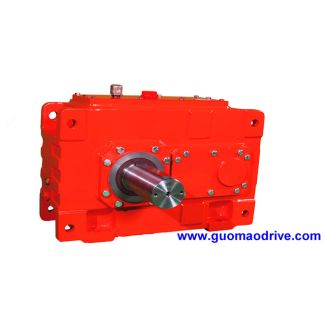

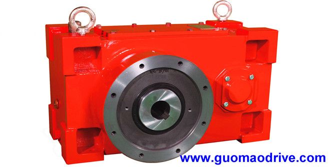
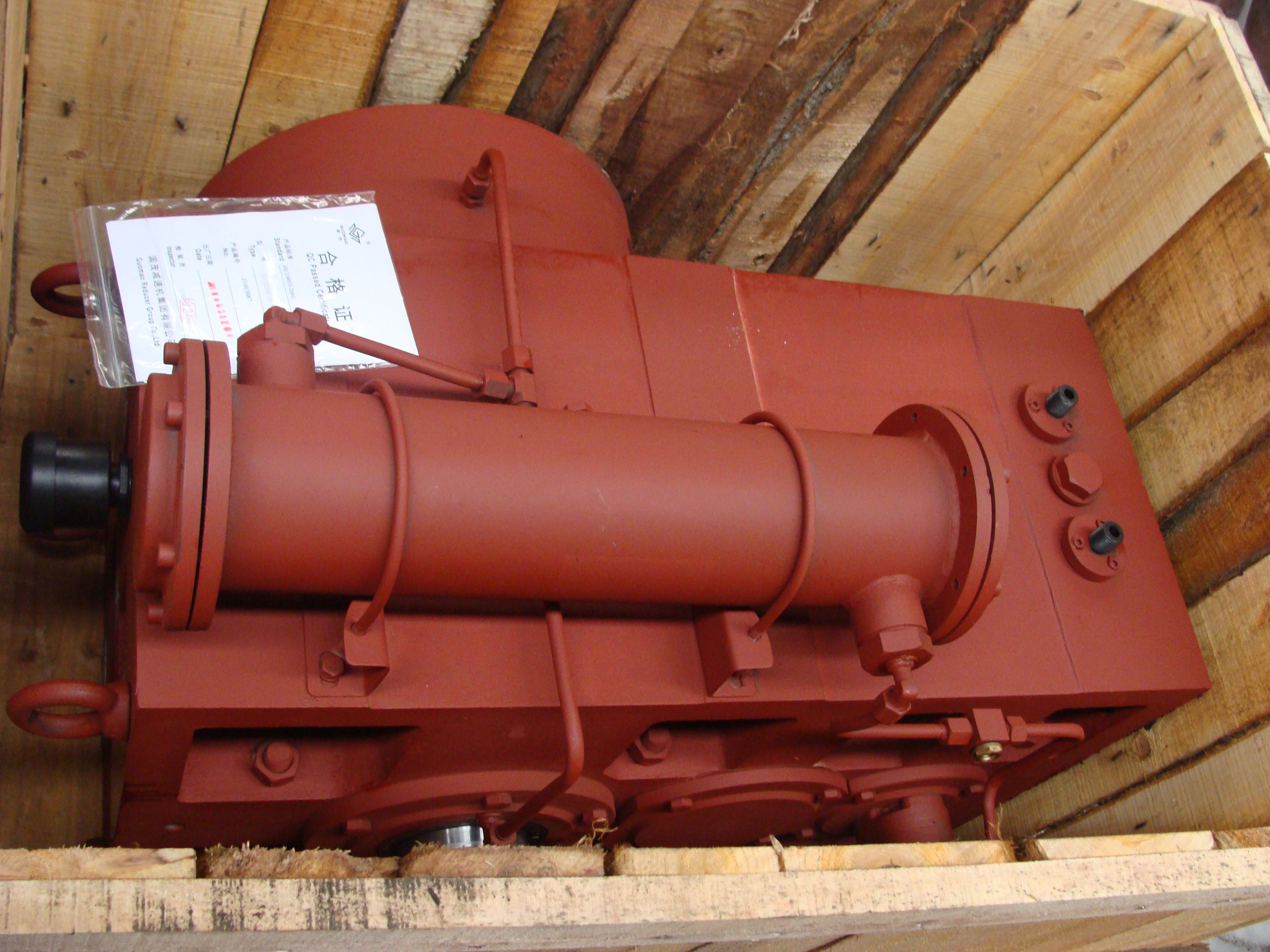
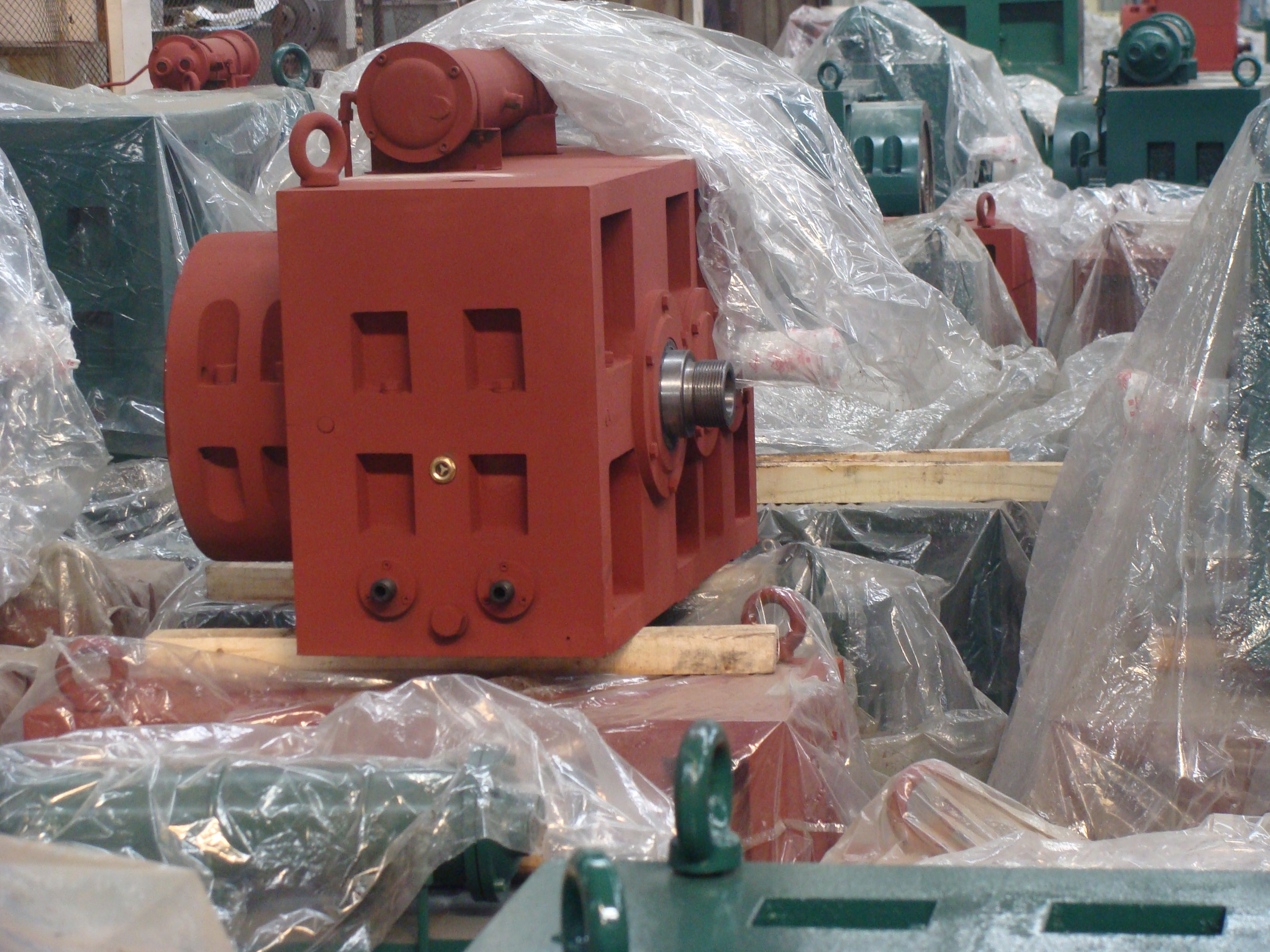

Flender/Flender Gear Units/Helical speed reducer H3
connected to these elements, the relative positions of the pinion and gear teeth and, hence the meshing conditions, the contact pattern and consequently the stresses on the gear members are changed. It is therefore essential to include the environment of
  the gear in stress analysis. The factors include displacements and tilting of the pitch cones due to: deection of the
  shafts, bearings, gear bodies and housing bearing clearance positional deviations of the bearing bores caused in manufacturing errors in gear
  assembly Load-dependent deections are caused by applied loads including torque, tooth forces of the bevel gear stage, and additional loads on the shafts such as forces of cylindrical gear stage, shear forces and bending moments at the ends of the shafts. The relative positions of the pinion and wheel are, for example, described by the four possible forms in axis displacement and their deviations in hypoid bevel gear set (Fig. 4.: shaft angle shaft angle deviation hypoid offset hypoid offset deviation pinion apex distance tz1 pinion axial displacement wheel apex distance tz2 wheel axial displacement Fig. 4.3 Displacements of the gear axes1 4 Load Capacity and Efciency The non-linear relationship between load and deection can be taken into account by section-wise linearization or by an iterative procedure. 4.4.3.4 Calculating Tooth Flank Stress The maximum normal stress acting in the contact area between meshing tooth anks, also known as Hertzian stress, is employed as an equivalent variable in characterizing tooth ank stress, as in [ DIN3 ,DIN3 ,ISO6 ,ISO1 ] (Fig. 4.. In manner similar to the calculation of local tooth deection, the original Hertzian model of two contacting cylinders is modied in model of two contacting inclined cones pointing away from one another, and subdivided into sections (cylindrical segments). The local ank stress resulting from the load determined for the ith ank region Fni(normal force) may be calculated as: Hi
| Model Type | Helical speed reducer H3 |
|---|---|
| Gear Type | Helical Gear |
| Weight (kg) | 13200.000000 |
| Ratio Range | 1 : 25…100 |
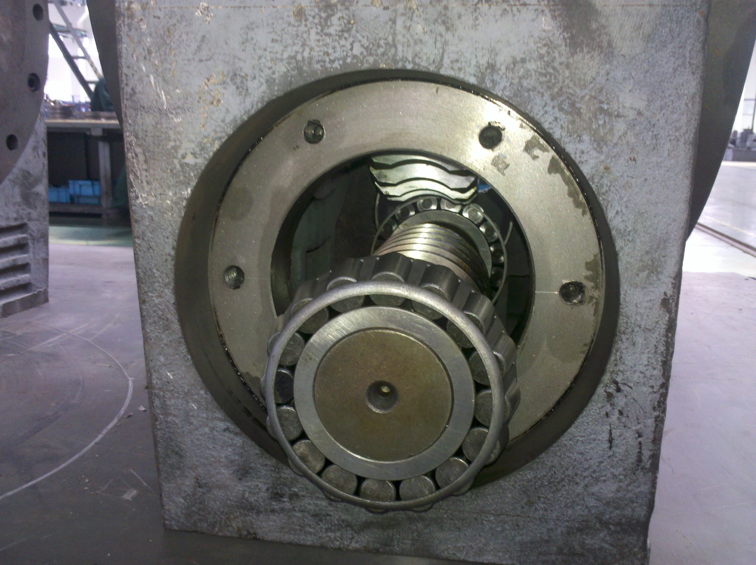
| Low Speed Output | Solid shaft with parallel key acc. to DIN 6885/1 with reinforced spigot |
| Nominal Torque | 725000 Nm |
| Mounting Arrangements | Horizontal mounting position |
| Manufacturer | Flender de Colombia |
| Country of Manufacture | Libya |
| Data Sheet & Drawings | H3VH-24-C flender penig Helical speed reducer H3 |
Related Products