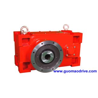

Flender/Flender Gear Units/Helical gear unit H3
cone toward tooth which is at the 1 clock position. If the tooth, seen from front to back, curves to the right, the gear has right hand of spiral, and vice versa. The concave ank is normally on the right
  side of the tooth on right handed bevel gears, and on the left side of the tooth on left handed
  bevel gears (sees Fig. 2.. In the special case of an inverse spiral, this situation is reversed [ SEIB0 ].
  Fig. 2.1 Dedendum angle modication. 1 dedendum angle modication, 2 mean pitch diameter dm1of the pinion, 3 mean pitch diameter m2of the wheel, 4 pitch angle 1of the pinion, 5 pitch angle 2of the wheel, 6 mean radius mPof the generating crown gear Fig. 2.1 Denition of the hand of spiral. 1 right hand, 2 left hand, 3 viewed from the pitch cone apex2.2 Gear Geometry 2 2.2.4.5 Drive and Coast Tooth Flanks On spiral bevel gears with positive hypoid offset, load conditions are favorable if the concave tooth ank of the pinion drives the convex tooth ank of the wheel (seeSect. 3.4.2 ). Usage in car axle drives has led to the choice of this ank of the pinion tooth for the drive mode, .. when the engine is moving the vehicle forward. Inversely, the convex tooth ank of the pinion is loaded when in coast mode,.. when the engine brakes the moving vehicle. From the preceding considerations,the tooth anks on all spiral bevel gear sets, with or without hypoid offset, receivethe following designations: pinion concave flank drive flank convex flank coast flank wheel convex flank drive flank concave flank coast flank 2.2.4.6 Contact Ratio Similarly to cylindrical gears, the contact ratio describes the average number of teeth which are simultaneously engaged. distinction is drawn between the prolecontact ratio , which results from the working height of the prole, and the overlap ratio , which is determined by the helix or spiral angle. The total contact ratio is the sum of these two parameters. The relationships are illustrated in Fig.2.1. The sum of the contact and overl
| Model Type | Helical gear unit H3 |
|---|---|
| Gear Type | Helical Gear |
| Weight (kg) | 11880.000000 |
| Ratio Range | 1 : 22.4…90 |
| Low Speed Output | Solid shaft with parallel key acc. to DIN 6885/1 with reinforced spigot |
| Nominal Torque | 640000 Nm |
| Mounting Arrangements | Horizontal mounting position |
| Manufacturer | Flender Brasil Ltda |
| Country of Manufacture | Kyrgyzstan |
| Data Sheet & Drawings | H3VH-23-C flender sa Helical gear unit H3 |
Related Products