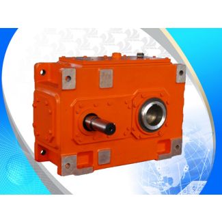

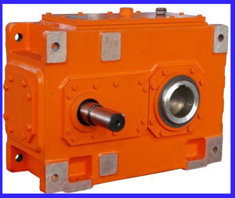
Flender/Flender Gear Units/Helical gear units H3
cooling with cooling coil, or with fan and cooling coil) Prime mover factor f2 Electric motors, hydraulic motors, turbines1.0 Piston-driven machines 4 - 6 cylinders, degree of uniformity 1 : 1 to 1: 2.2 Piston-driven machines 1 - 3 cylinders,
  degree of uniformity 1 : 1.5 Peak torque factor f3 Load peaks per hour 1 - 5 6 - 3
  3 - 1 > 1 Steady direction of load 0.5 0.6 0.7 0.8 Alternating direction of load 0.7 0.9 1.1
  1.2 Ambient temperature 1 1 2 2 3 3 4 4 5 f4 for PAO oil filling1.1 1.0 1.0 0.9 0.8 0.8 0.7 0.6 0.6 f4 for gear units filled with mineral oil0.7 0.7 0.7 0.6 0.6 0.5 0.5 0.4 0.4Ambient temperature 1 1 2 2 3 3 4 4 5 f5 for PAO oil filling1.0 1.0 1.0 0.9 0.9 0.9 0.8 0.8 0.8 f5 for gear units filled with mineral oil0.8 0.7 0.7 0.7 0.7 0.6 0.6 0.6 0.6 Altitude (meters above sea level) Up to 1 Up to 2 Up to 3 Up to 4 Up to 5 Altitude factor f6.0 0.9 0.9 0.8 0.8 Altitude (meters above sea level) Up to 1 Up to 2 Up to 3 Up to 4 Up to 5 Altitude factor f7.0 0.9 0.9 0.9 0.9 Flender GmbH 2NER GROUP CO.,LIMITED Germany sogears HB series gearbox 3/1 Flender MD 2.1 2 3Design of the gear units Guidelines for selection Designs for crane applications Overview The Flender gear units are an economical solution for industrial and indoor cranes. The options often required for crane applica- tions, such as high speed and/or low speed shafts on both sides, are available in the standard portfolio. Service factors for crane systems For the use of gear units with variable loads such as those generally present in crane systems an FEM classification is recommended. The driven machine factor f1 and the peak torque factor f3 corresponding to the mechanism group M1 to M8 depending on the load (collective classes L1 to L and the duration of operation (operating classes T0 to T can be found in the tables below. Regardless of the table values, recalculation provides the basis for Flender for the right solution, because in many cases significantly smaller di
| Model Type | Helical gear units H3 |
|---|---|
| Gear Type | Helical Gear |
| Weight (kg) | 625.000000 |
| Ratio Range | 1 : 31.5…112 |
| Low Speed Output | Solid shaft with parallel key acc. to DIN 6885/1 with reinforced spigot |
| Nominal Torque | 27200 Nm |
| Mounting Arrangements | Vertical mounting position |
| Manufacturer | A. FRIEDR. FLENDER AG |
| Country of Manufacture | Peru |
| Data Sheet & Drawings | H3-VV-8B flender ag bocholt Helical gear units H3 |
Related Products