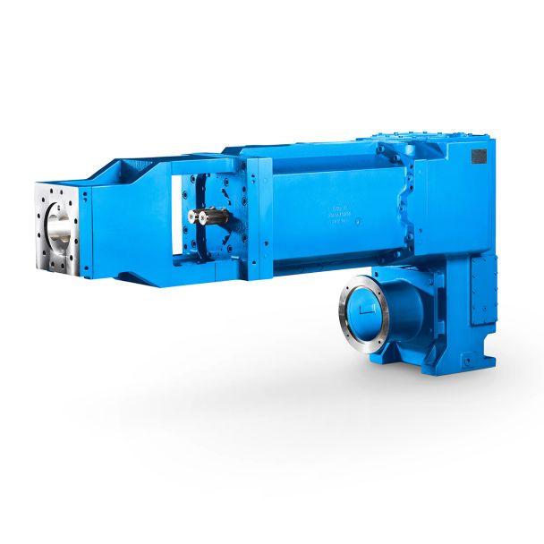

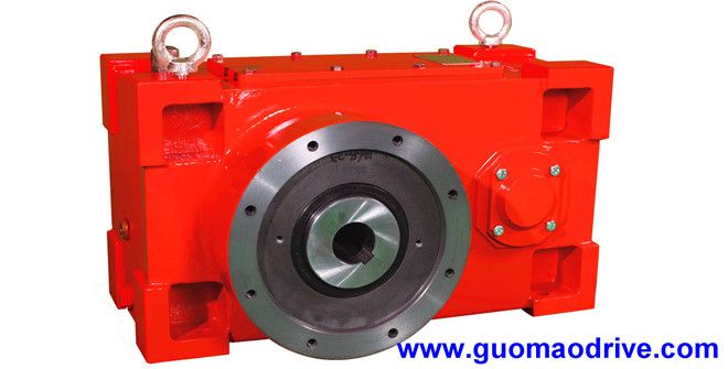
Helical speed reduction gearboxes H3 flender south africa contact details H3-VV-27-A
In stock
SKU
H3-VV-27-A
$486,428.57
Flender/Flender Gear Units/Helical speed reduction gearboxes H3
d shaft diameter, chain type and length, chain sprocket di - ameter and speed are displayed on the screen as output results. Additionally, this screen includes icons showing chain characteristic values, the overall appearance of the elevator, and shaft sizing.
  When the shaft sizing button is clicked, the visual structure of the shaft along with nu - merical values is
  displayed on the screen as shown in Fig - ure 3, which illustrates the drive system shaft sizing vi -
  sualization. Clicking on the chain properties button will display the chain characteristic values table on the screen as shown in Figure 4. When the general appearance but - Figure 1. Program main window Figure 2. Microsoft visual studio # program main window Uluslararas Mhendislik, Tasarm ve Teknoloji Dergisi / International Journal of Engineering, Design and Technology, 2: 6(Onur Gven, Mehmet Ali Altunbaak ton is clicked, the parts constituting the elevator and the general appearance are displayed on the screen. Clicking on the Project button, located next to the bucket type output, chain type output, and chain sprocket output, will display the project drawing details on the screen. 4.1. Material Selection Computer-aided elevator calculations have been per - formed for materials such as clinker, coal, cement, fari - na, ground limestone, slag, fly ash, limestone, sand, salt, and coke. By selecting the name of the material from the dropdown menu, the program obtains the specific grav - ity value of the material from the table and includes this value in the calculations. 4.2. Capacity Selection In the selection of capacity, the capacity table shown in Figure 5, obtained through practical applications, expe - riences, and tests, has been utilized. The capacity values in this table have been incorporated into the program. The capacity values highlighted in yellow represent the most suitable ergonomic capacity values created consid - ering operating conditions and material properties. S
| Model Type | Helical speed reduction gearboxes H3 |
|---|---|
| Gear Type | Helical Gear |
| Weight (kg) | 22700.000000 |
| Ratio Range | 1 : 22.4…90 |
| Low Speed Output | Solid shaft with parallel key acc. to DIN 6885/1 with reinforced spigot |
| Nominal Torque | 1230000 Nm |
| Mounting Arrangements | Vertical mounting position |
| Manufacturer | WALTHER FLENDER GMBH |
| Country of Manufacture | Cambodia |
| Data Sheet & Drawings | Helical speed reduction gearboxes H3 flender south africa contact details H3-VV-27-A |
Related Products