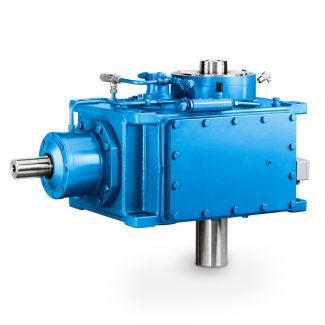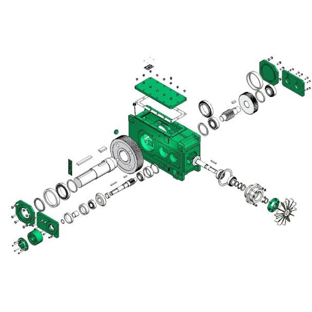
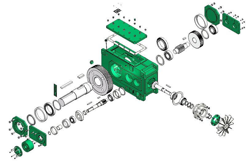
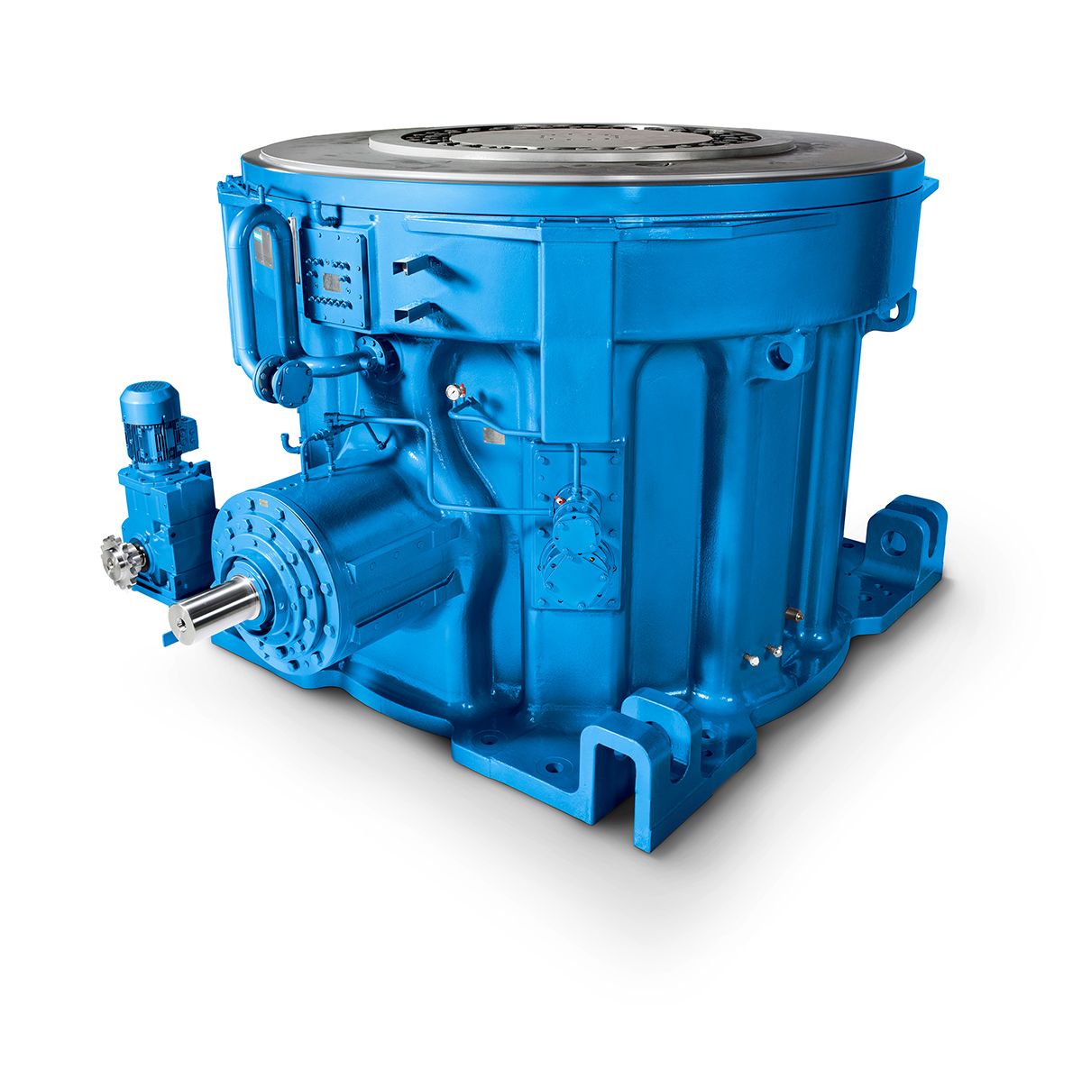
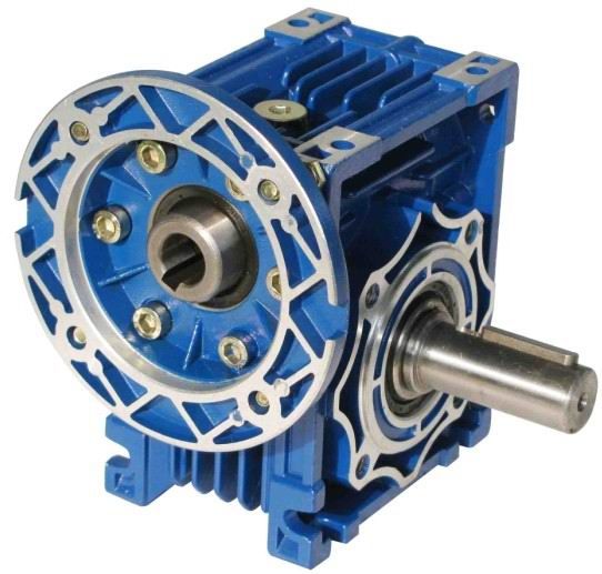
H3-SV-17-D accouplement n eupex Helical gear units H3
In stock
SKU
H3-SV-17-D
$97,714.29
Flender/Flender Gear Units/Helical gear units H3
cessityofwastecomminution,andthefactthata large proportion (approx 8O0/)ofthesolid residues takes the form of flue ash and filter dust and thus has to be special1 treated, requires extensive investigation Waste pyrolysis, in turn, has to be precisely matcheJto the feedstock In particular, it must
  be established whether the goal of waste treatment is utilisation of the waste, or its disposal 3.1 Pyrolysis The plant
  and process-related analysis showed the first signs that, despite the respective com- pany-specific plant control systems, all pyrolysis processes have
  the same fundamental, syste- matic structure On the basis of this structure, there are four basic structures in which the exist- ing pyrolysis processes can be classified Pyrolysis processes with direct combustion of the resultant pyrolysis gas, the Babcock process and the Krupp-Polysius process I1 Pyrolysis processes with conditioning of the pyrolysis gas and use of the resultant clean gas as fuel for gas engines or combustion in boiler plant, the KWU clean-gas variant and the PKA process 1 Pyrolysis processes with joint pyrolysis gas and pyrolysis coke combustion, the KWU low-temperature combustion process IV Pyrolysis processes with condensation of the pyrolysis gas in order to recover pyrolysis oils, BBC plastics pyrolysis, the Energas process, the MVU Rotopyr process and the Noell reguse pyrolysis process All four basic structures include processing of the feedstock, generation and utilisation of the pyrolysis gas, as well as dumping of the resultant solid residues This system outlines the differ- ent company-specific designs according to mutual characteristics and thus facilitates the assessment of pyrolysis from the point of view of waste technology 3.2 Fluidised-bed combustion The develo ment of fluidised-bed technolo yas combustion system led to different, com- pan -specifc design variants The variants wkh operate with pressure-charged reactor and constitute an
| Model Type | Helical gear units H3 |
|---|---|
| Gear Type | Helical Gear |
| Weight (kg) | 4560.000000 |
| Ratio Range | 1 : 22.4…90 |
| Low Speed Output | Solid shaft with parallel key acc. to DIN 6885/1 |
| Nominal Torque | 200000 Nm |
| Mounting Arrangements | Vertical mounting position |
| Manufacturer | A. Friedr. Flender AG & Co. KG |
| Country of Manufacture | China |
| Data Sheet & Drawings | H3-SV-17-D accouplement n eupex Helical gear units H3 |
Related Products