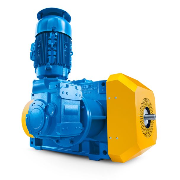


Flender/Flender Gear Units/Helical speed reducers H3
dividual tooth mesh transmission errors are shifted vertically by their respective component incumulative pitch error, while retaining their basic form. By ltering the entiresignal, it is possible to obtain curve like the one shown in the bottom-left halfof Fig. 5.2.
  It is apparent from more detailed analysis of the individual tooth mesh transmission errors that tooth engagement is either shortened
  or prolonged.2 5 Noise Behavior Apart from cyclical changes in the meshing period, further effect of cumulative pitch error is
  cyclical change in the min-max values of the individual tooth mesh transmission errors [ FAUL6 ], [NAUM6 ], [LAND0 ]. Translating these observations into signal processing terminology, cumulative pitch error may be said to cause amplitude and frequency modulations of tooth mesh transmission error. Such modulations are expressed spectrally by sidebands in the meshing order of the type shown in the bottom-right half of Fig. 5.2. The distance between the lower and upper sidebands and the meshing order are directly correlated with the period of the cumulative pitch error. In single sinusoidal cumulative pitch error curve, the amplitude and the duration of an engagement respectively exhibit one maximum and one minimum during one revolution. In consequence, the sideband distance is exactly one mesh order (lower sideband 1th wheel order, mesh order 1th wheel order, upper sideband 1th wheel order). cumulative pitch error with triple sinusoidal form produces three minima and three maxima per revolution for mesh amplitude and period (Fig. 5.. The distances of the top and bottom sidebands then rise from one to three wheel orders, as can be seen from the bottom-right half of Fig. 5.2. Detailed discussions of the basic principles in amplitude and frequency modulation may be found in [DALE8 ], [REIC6 ] and [ THOM8 ]. Fig. 5.2 Transmission error with long- and short-term components5.3 Noise Excitation Governed by Manufacturing 2 Topography Deviations Un
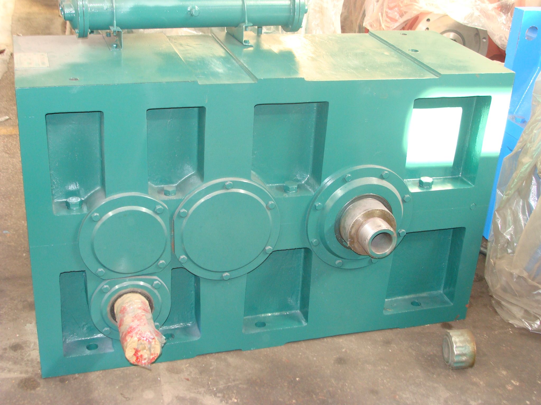
| Model Type | Helical speed reducers H3 |
|---|---|
| Gear Type | Helical Gear |
| Weight (kg) | 540.000000 |
| Ratio Range | 1 : 25…90 |
| Low Speed Output | Hollow shaft with keyway acc. to DIN 6885/1 |
| Nominal Torque | 21700 Nm |
| Mounting Arrangements | Horizontal mounting position |
| Manufacturer | Flender Ibérica S.A. |
| Country of Manufacture | Ireland |
| Data Sheet & Drawings | Helical speed reducers H3 n eupex a280 H3-HH7-B |
Related Products