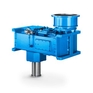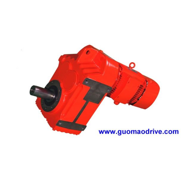
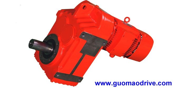
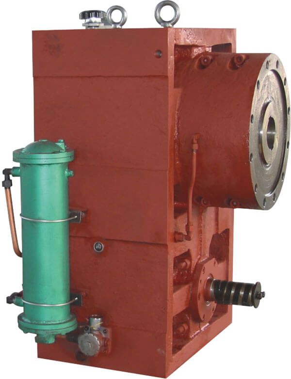


Flender/Flender Gear Units/Helical gear reducer H3
direction of load; .. hoisting gears, traveling gears, etc.), coupling design is to be checked in accordance with the respective valid coupling brochure. For deviating couplings, please consult Flender. For mounting dimensions for IEC motors EN 5 (View ), see
  page 1/3. Helical gear unit in design , , on request only. Not in connection with Taconite or labyrinth seal
  at the drive shaft.G_MD2_XX_0X Zf G_MD2_XX_0ZD 1 2h1 l1 l2 h2skG_MD2_XX_0X Zf G_MD2_XX_0Z 2 1 l1 l2 h2h1 sk Flender
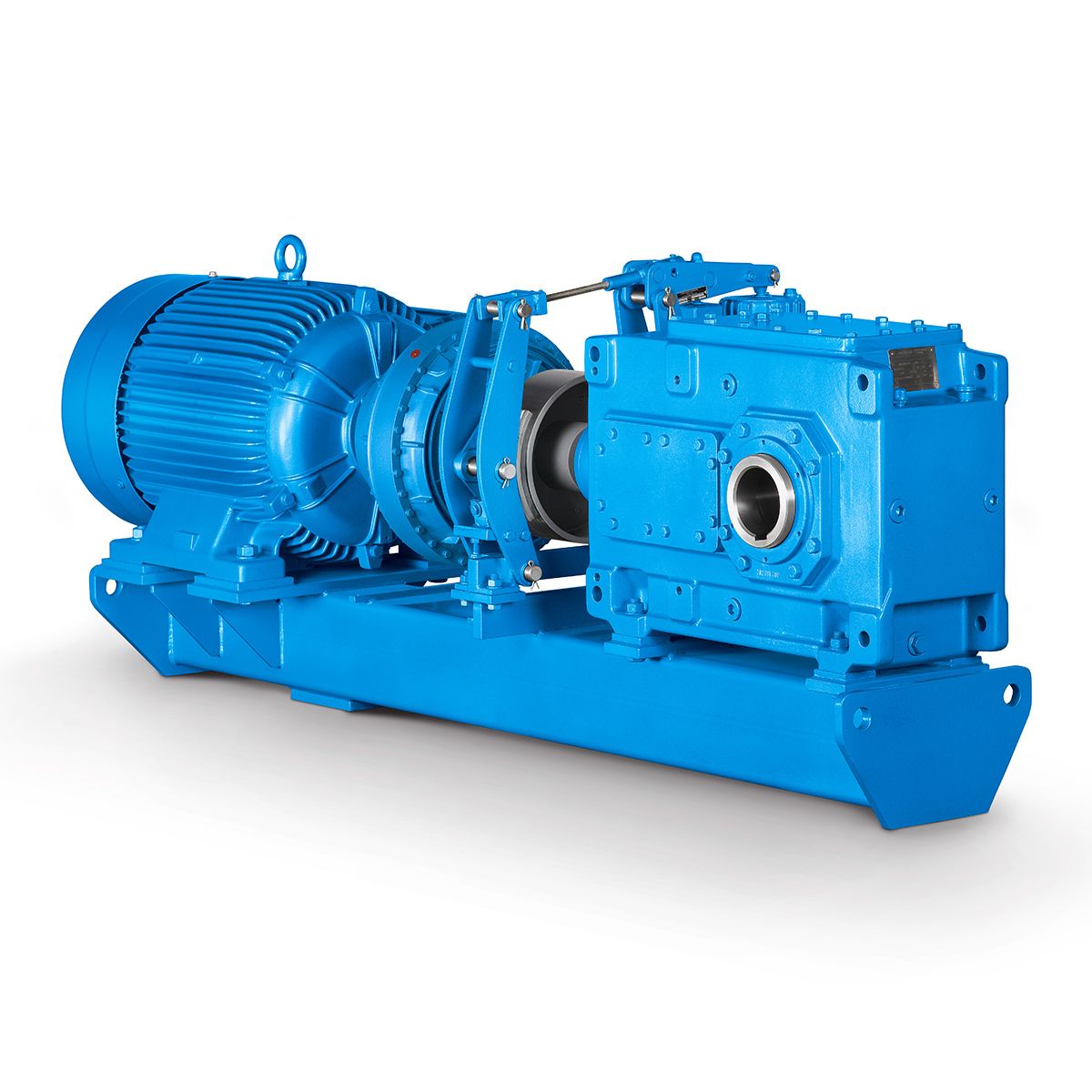
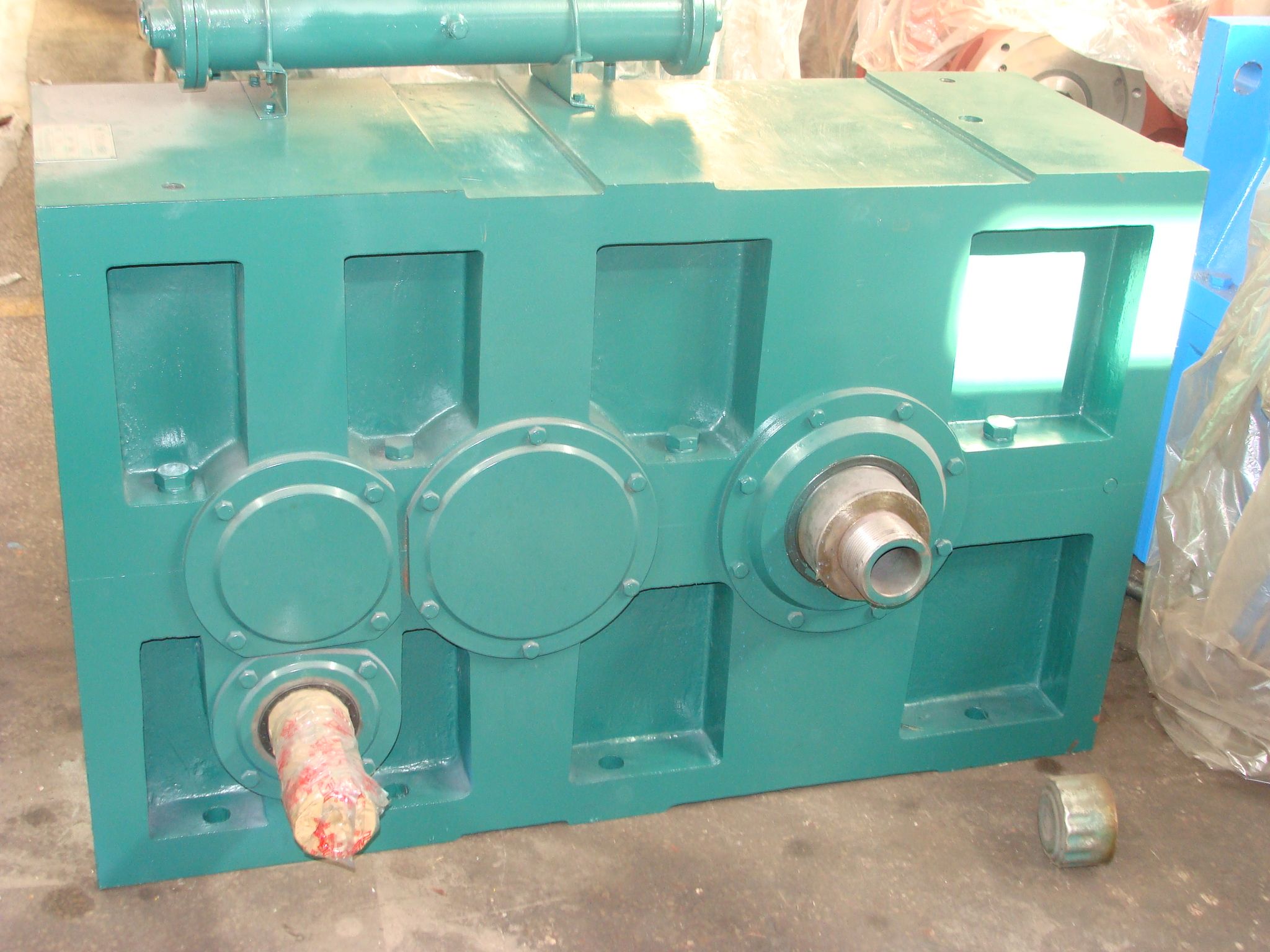
  GmbH 2NER GROUP CO.,LIMITED Germany sogears HB series gearbox 1/2 Flender MD 2.1 2 1Options for installation and add-on parts Motor bell housing for IEC standard motor with -EUPEX coupling Helical gear unit, type H4, gear unit sizes 7 to 1 Design (continued) Dimensions in mm Size Ratios iN 1 - 1 (sizes 7, 9, 1 - 2 (sizes 8, 1, 1 - 1 (sizes 1, 1, 1 - 2 (size 1 - 2 (sizes 1, Ratios iN 2 - 3 (sizes 7, 9, 2 - 4 (sizes 8, 1, 2 - 3 (sizes 1, 1, 2 - 4 (size 2 - 4 (sizes 1, IEC motor -EUPEX skl1 D1l2 D2h1 h2 -EUPEX skl1 D1l2 D2h1 h2 7/8 1 B8 3 3 2 3 2 -7 6 2 1 B8 3 3 2 3 2 -7 6 2 1 B9 3 3 3 3 3 -7 8 3.5 1 B1 3 5 3 5 4 -6.5 1 3.5 B1 3 5 2 5 4 -1 1 3.5 1 B1 3 5 3 5 4 -1 4.5 3.5 9/1 1 B9 3 3 2 3 3 -1 1.5 3.5 1 B1 3 5 3 5 4 -6.5 1 4.5 B1 3 5 2 5 4 -1 1.5 4.5 1 B1 3 5 3 5 4 -1 7.5 4.5 B1 3 5 2 5 4 -2 7.5 4.5 2 B1 4 6 3 6 5 -1 1.5 4.5 2 B1 4 7 3 7 6 -1.5 2 4.5 1/1 1 B1 3 5 3 5 4 0 4.5 4.5 1 B1 3 5 4 5 4 -7 3.5 4.5 B1 3 5 3 5 4 0 4.5 4.5 2 B1 4 6 4 6 5 -6.5 1 4.5 B1 4 6 3 6 5 0 1.5 4.5 2 B1 4 7 4 7 6 0 6.5 5.5 B1 4 7 3 7 6 -3 2.5 5.5 2 B1 4 7 4 7 6 0 6.5 5.5 1/1 1 B1 3 5 3 5 4 -9 1.5 5.5 1 B1 3 5 3 5 4 -3.5 1 5.5 2 B1 4 6 5 6 5 -2 8.5 5.5 B1 4 6 3 6 5 0 4.5 5.5 2 B1 4 7 5 7 6 -9.5 2 5.5 B1 4 7 3 7 6 -4 1.5 5.5 2 B1 4 7 5 7 6 -7.5 2 5.5 B1 4 7 3 7 6 -4 1.5 5.5 2 B2 4 8 5 8 7 0 1 5 3 1/1 2 B1 4 6 5 6 5 0 3.5 5.5 2 B1 4 7 6 7 6 -1.5 9 6.5
| Model Type | Helical gear reducer H3 |
|---|---|
| Gear Type | Helical Gear |
| Weight (kg) | 320.000000 |
| Ratio Range | 1 : 25…90 |
| Low Speed Output | Hollow shaft with keyway acc. to DIN 6885/1 |
| Nominal Torque | – Nm |
| Mounting Arrangements | Horizontal mounting position |
| Manufacturer | A. FRIEDR. FLENDER AG |
| Country of Manufacture | Haiti |
| Data Sheet & Drawings | Helical gear reducer H3 n eupex b 95 H3-HH5-B |
Related Products