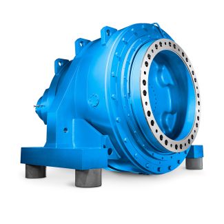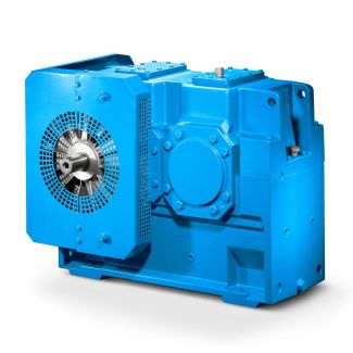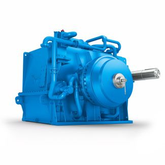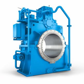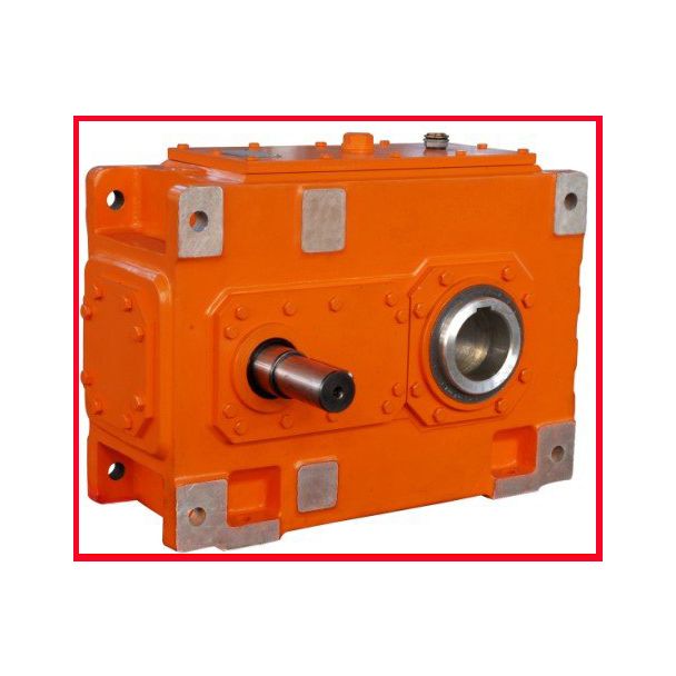
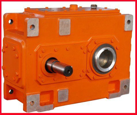
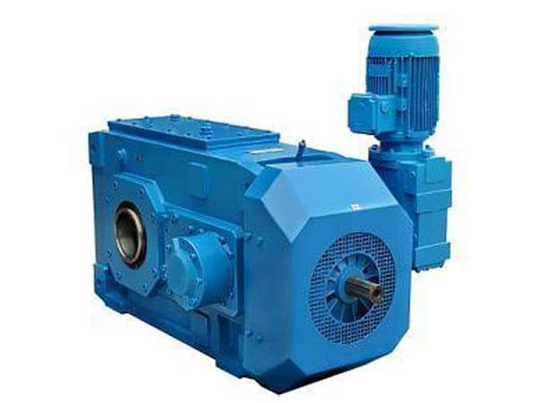
H3-FV19-B www flender com Helical gear reducer H3
In stock
SKU
H3-FV19-B
$143,571.43
Flender/Flender Gear Units/Helical gear reducer H3
especially suitable because they correlate directly with the form and position of the contact pattern. For example, to displace the contact pattern from the smaller to the larger diameter (toe to heel), the spiral angle difference is reduced; to lengthen
  the contact pattern in the face width direction, the lengthwise crowning is reduced. 3.3.4 Additional Motions This section describes the
  effects, on the ease-off, of higher order coefcients in the manufacturing kinematics. Visualization of the contact lines between the tool
  and the tooth ank during the generating process, Fig. 3.1, st em eo fo . Profile crowning Lengthwise crowning Pressure angle change Spiral angle change Bias change Fig. 3.1 Parameters for the quantitative description of any ease-off topography Fig. 3.1 Position of the contact lines between the tool and the tooth ank7 3 Design Figure 3.1 shows the position of the contact lines between the tool and the tooth ank, termed generatrixes, for generated pinion. Additional motions dependent on the respective cradle angle will act on all points of the generatrixes belonging to this, which are seen advancing diagonally from line to line across the tooth ank. In consequence, additional motions of the type created by higher order coefcients will modify the shape of the ank in the same diagonal direction. Modications along each generatrix can be achieved solely through the form of the tool. This principle applies irrespectively of the system of base functions employed in the manufacturing kinematics. For the case of series function of the tool rotation dependent on the cradle position or roll angle , the polynomial coefcients of the function produce the ank modications shown in Fig. 3.1: abm m 2 ...m 6:3 Tooth ank form modications are of particular interest for manufacturing methods in which both anks of tooth slot are machined in single cut. In such cases, the additional motions act on both anks, but in partly different di
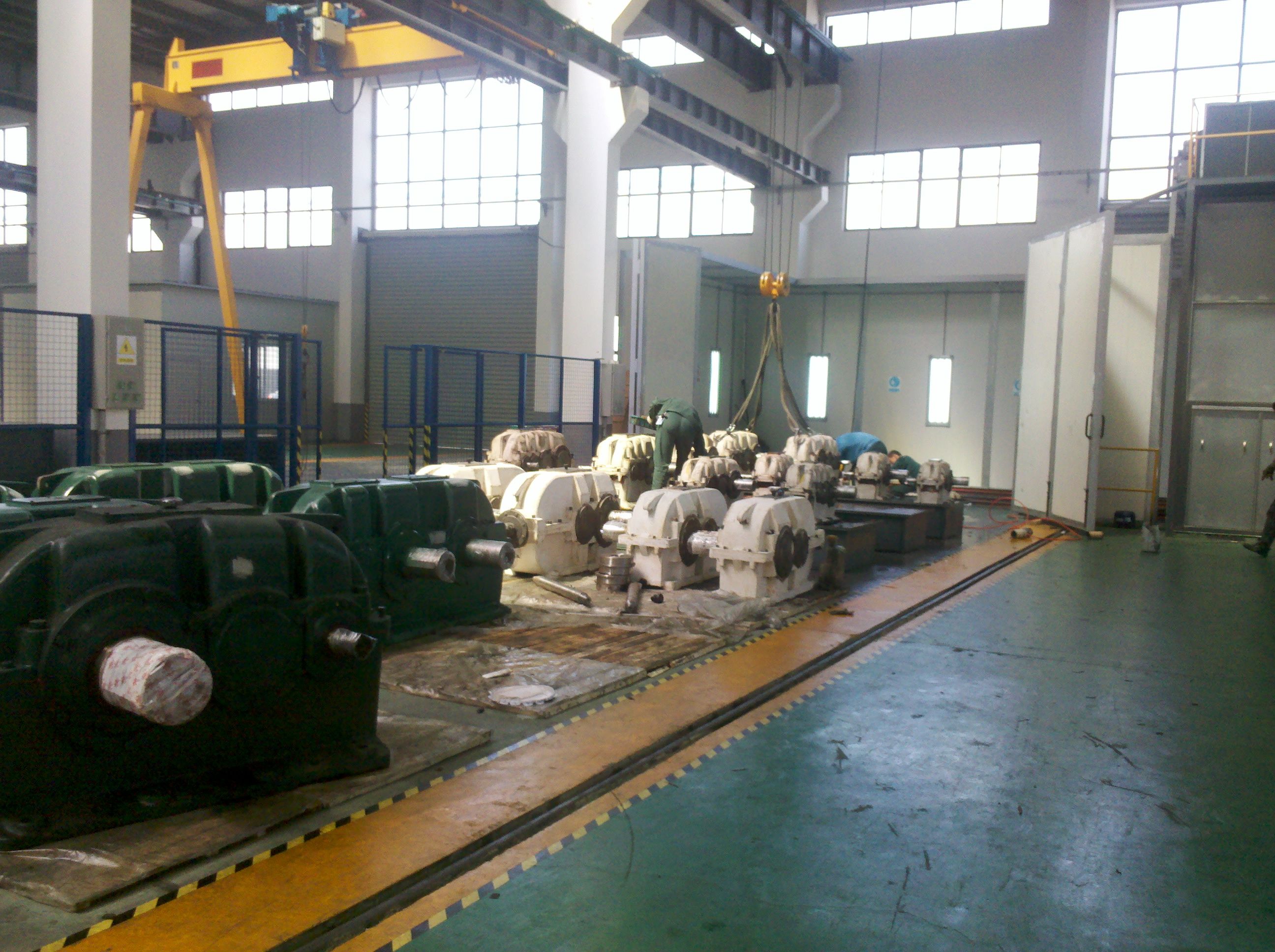
| Model Type | Helical gear reducer H3 |
|---|---|
| Gear Type | Helical Gear |
| Weight (kg) | 6700.000000 |
| Ratio Range | 1 : 22.4…90 |
| Low Speed Output | Flanged shaft |
| Nominal Torque | 300000 Nm |
| Mounting Arrangements | Vertical mounting position |
| Manufacturer | Flender Industriegetriebe GmbH |
| Country of Manufacture | Saudi Arabia |
| Data Sheet & Drawings | H3-FV19-B www flender com Helical gear reducer H3 |
Related Products