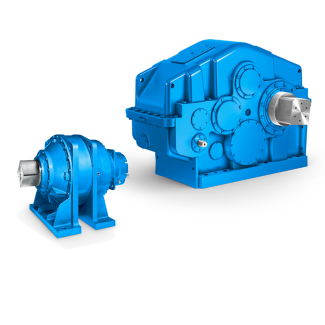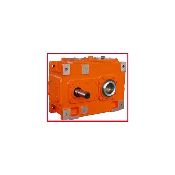

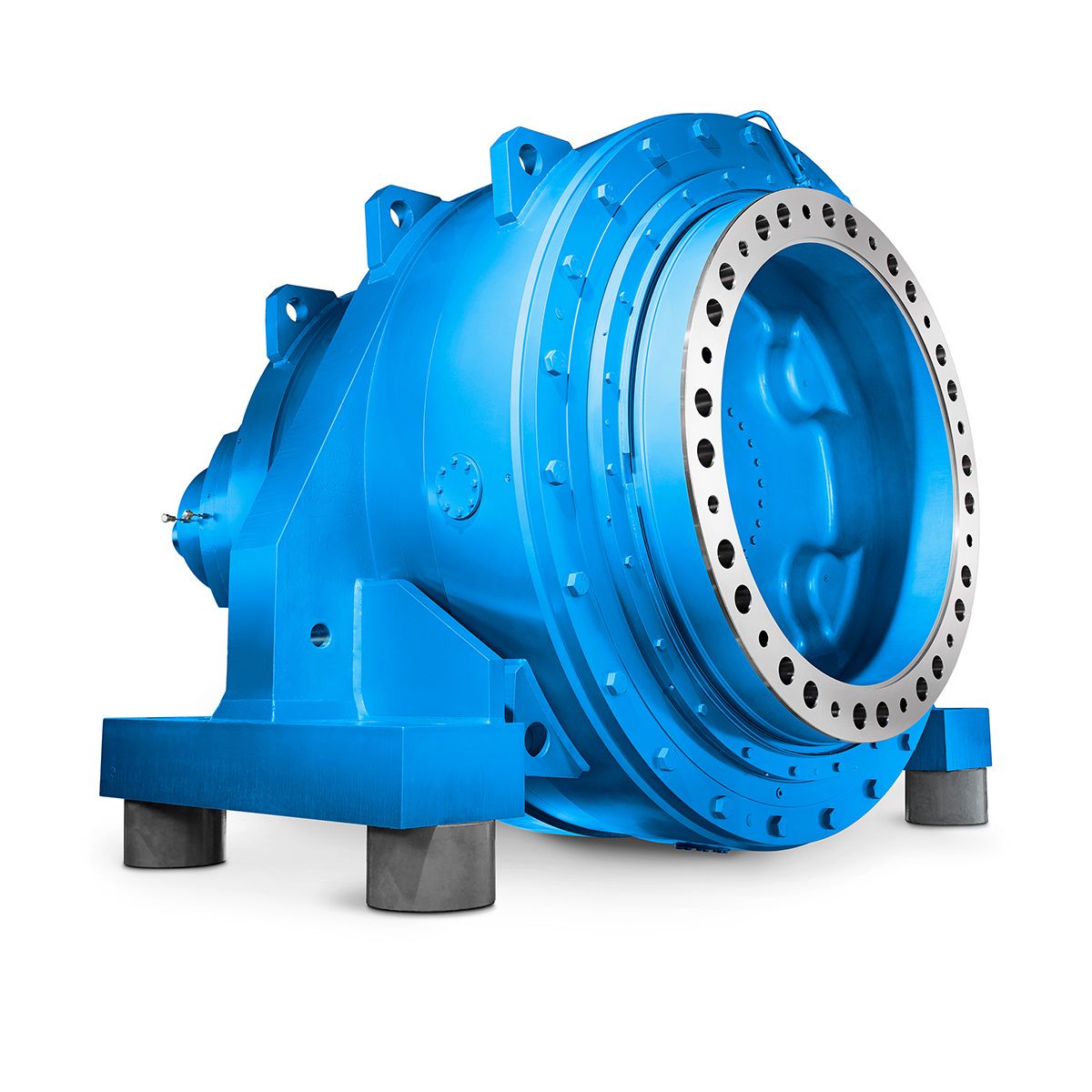


H3-FH-17-A rwn coupling catalogue Helical gear reducers H3
In stock
SKU
H3-FH-17-A
$97,714.29
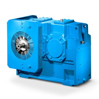
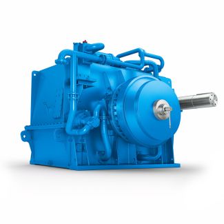
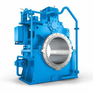
Flender/Flender Gear Units/Helical gear reducers H3
er. Each section has its own set of sieves. These sieves arestacked up, one above the other, and the number of sieves in given stack may vary, depending on the sifter type, anywhere from 1 to 3. sifter generally comes
  with four, six, or maximum of eight sections (Fig. 2a). These sections are located within boxand there are two boxes
  in sifter containing an even number of sections. The two boxesare joined together with driving mechanism in the center. The
  boxes are suspended fromgirders above by four sets of canes at each end of the corner. Canes are used for suspensionas they are strong and exible to allow free swinging of the sifter. The drive consists of vertical countershaft that has weights attached to it in the center. As the shaft is rotated by motor-driven pulley from the top the sifter with the counterbalanced weights beginto swing on horizontal plane. pencil fastened to the bottom end of the sifter woulddraw perfect circle. This indicates that the sifter is in balance. The diameter of the circlefor European sifter is 7 mm, and speed ranges from 2 to 2 rpm. North Americansifters have rotational diameter of 1 mm, with slower revolution of 1 rpm. sieve comprises wooden frame, over which screen cloth is stretched and secured either by means of staples or glue, and an outer frame consisting of collecting tray (see Fig. 2c). The sieve frame is inserted on this outer frame. The wooden sieve frame hasappropriate screen cloth on top, and on the bottom side coarse wire screen is in placeto hold plastic or cotton pad cleaners. As the sifter rotates the cleaners move aroundkeeping the underside of the sieve clean. Since the sieve frame is inserted on the outer 2 Sarkar () () () Fig. 2 () Plansifter; () series of plansifters; () sifter sieve. (Courtesy of Bu hler, Inc.) frame consisting of collecting tray, material that passes through the sieve is collected in this tray and is guided out of it through an opening along one side of the frame. Thematerial
| Model Type | Helical gear reducers H3 |
|---|---|
| Gear Type | Helical Gear |
| Weight (kg) | 4560.000000 |
| Ratio Range | 1 : 22.4…90 |
| Low Speed Output | Flanged shaft |
| Nominal Torque | 200000 Nm |
| Mounting Arrangements | Horizontal mounting position |
| Manufacturer | Flender Ltd., China |
| Country of Manufacture | Bulgaria |
| Data Sheet & Drawings | H3-FH-17-A rwn coupling catalogue Helical gear reducers H3 |
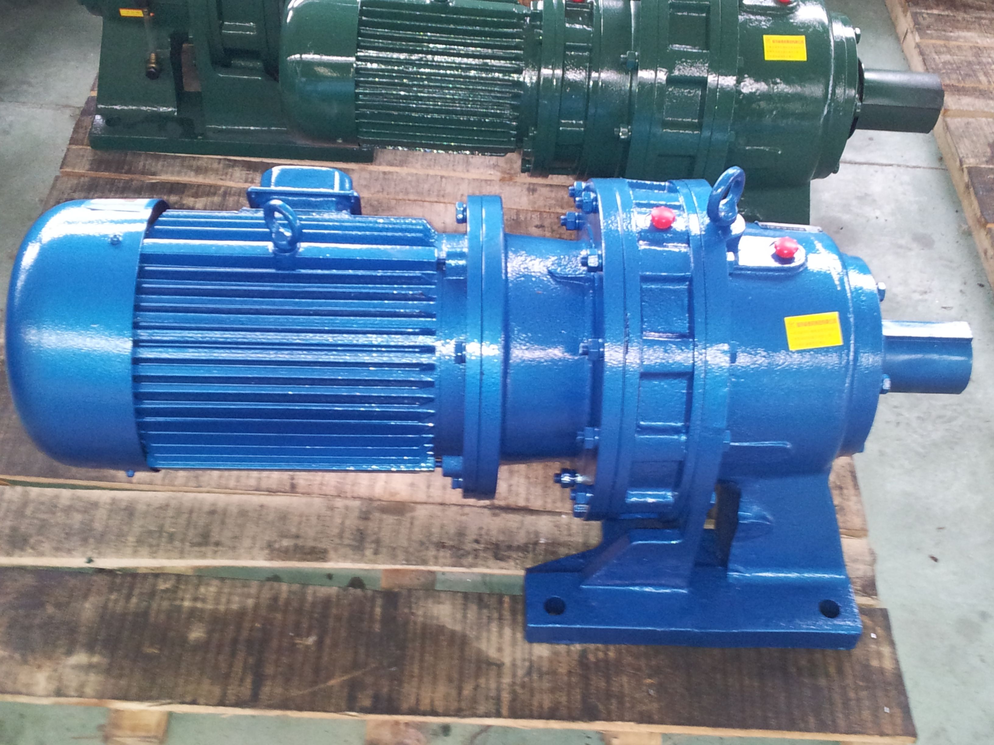
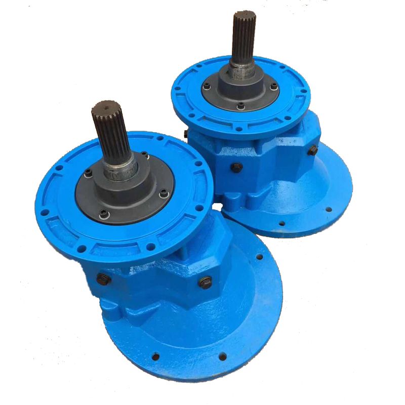
Related Products