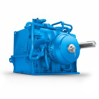
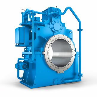
flender drives private limited kharagpur H3-DH7-B Helical gear units H3
In stock
SKU
H3-DH7-B
$11,571.43
Flender/Flender Gear Units/Helical gear units H3
e possible to select the number of pinion teeth. The rst approach is to maintain specic minimum number of crown gear teeth Pmin/C2 ...3. z1zPmin/C1sin 1u2/C1cosp 3:5 The following rule-of-thumb formula to determine the number of pinion teeth can be
  deduced for non-offset bevel gears with 9/C1shaft angle and given ratio e2/b2.5 3 Design z1de2/C1/C1Re2 b2/C1/C1 /C1cosm2 2/C1u/C1mmn/C1Re2 b2/C1/C1 3:6
  rough calculation of the mean normal module can be made from ratios e2/b2and b2/mmn. mmnRe2 Re2 b2/C1b2 mmn3:7 For the
  selection of the number of teeth, it is also necessary to observe the limitations of the machine tools manufacturing the gears in terms of feasibleminimum and maximum tooth numbers and maximum transmission ratios. Incontinuous indexing face hobbing processes, the number of teeth and the numberof blade groups should not be dividable by common number. If this were the case, the same blade group would always machine the same slot such that inaccuracies in the blade group would be reected directly in the pitch accuracy of the bevel gear. periodicity corresponding to the number of blade groups would then be evident inthe measured pitch deviation. Mean spiral angle m2In most manufacturing methods, it is possible to select the mean spiral angle (see Sect. 2.. Apart from the contact ratio, the spiral angle inuences tooth forces and hence bearing loads. Sometimes the spiral angle also hasan effect on the face and root angles (Duplex taper for example, see Sect. 2.2.4.2 ). For non-offset spiral bevel gears, the mean spiral angle should lie in range of 3 /C1 to 4/C1if there is no conicting experience or requirement. In most cases, spiral angle of 3/C1is usually chosen. For hypoid gears, the mean spiral angle on the wheel should be selected such as to ensure pinion spiral angle less than 5/C1in order to avoid problems at the toe or heel. Tool radius c0Tools for the different manufacturing methods being supplied in various sizes and categories, th
| Model Type | Helical gear units H3 |
|---|---|
| Gear Type | Helical Gear |
| Weight (kg) | 540.000000 |
| Ratio Range | 1 : 25…90 |
| Low Speed Output | Hollow shaft with shrink disk |
| Nominal Torque | 21700 Nm |
| Mounting Arrangements | Horizontal mounting position |
| Manufacturer | Flender de Mexico, S.A. de C.V. |
| Country of Manufacture | Mongolia |
| Data Sheet & Drawings | flender drives private limited kharagpur H3-DH7-B Helical gear units H3 |


