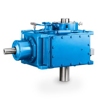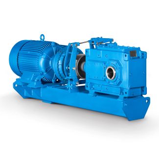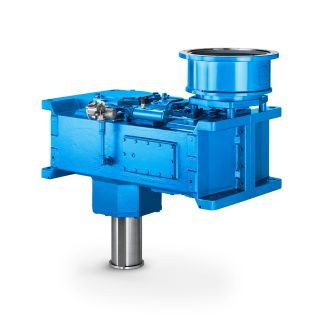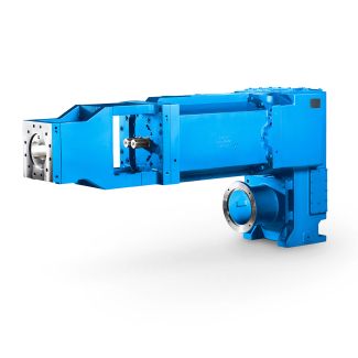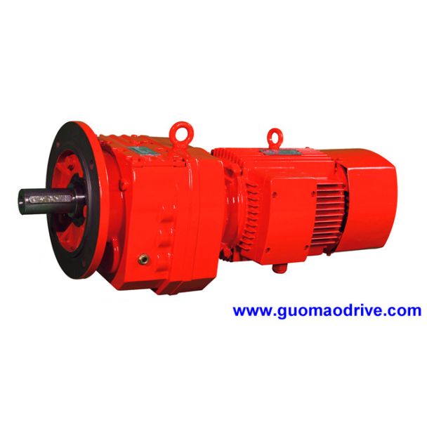

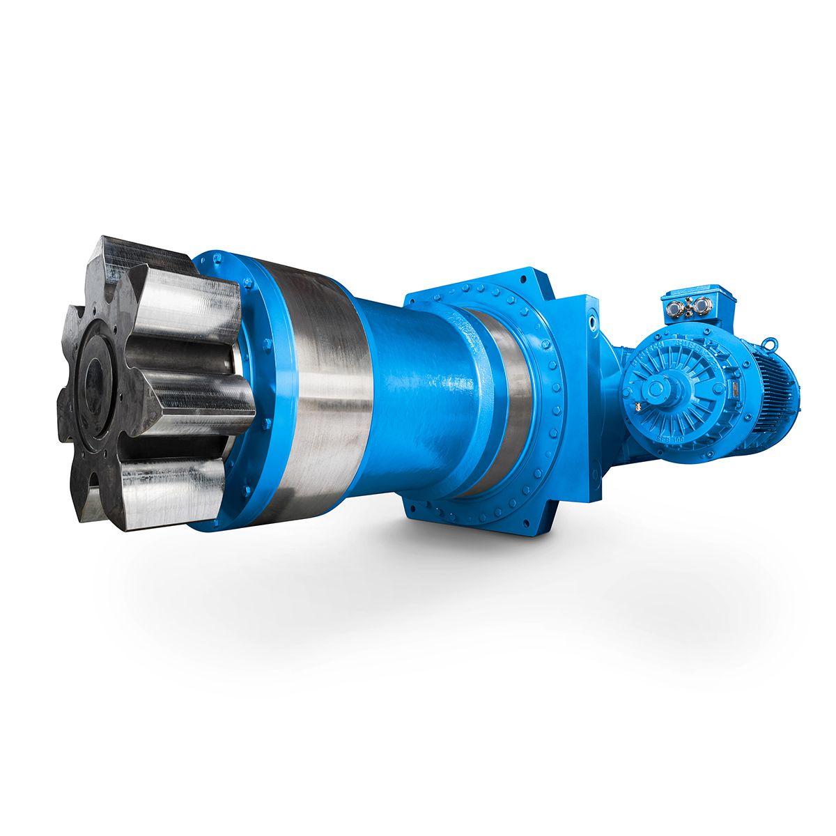

Helical gear Reduction Box H3 flender extruder gearbox H3-CH26A
In stock
SKU
H3-CH26A
$379,285.71
Flender/Flender Gear Units/Helical gear Reduction Box H3
damage the gear unit. Take the following precautions: The required joining temperatures can be found in the drawings in the operating instruc- tions for the coupling. Unless otherwise instructed, heat the coupling parts by an induction burner, with torch or
  in an oven. Use heat shields designed to protect against radiant heat in order to safeguard the shaft sealing rings
  against damage or heating to above 1C. Assembly 5.5 Couplings A5-0 en Edition 0/2 5Quickly fit the coupling parts on
  the shafts. The mounting dimensions can be found in the drawings in the operating instructions for the coupling. Gear units with hollow output shaft or output flange shaft There is no need to install the output-side coupling for gear units with hollow output shaft or flanged output shaft. Mount gear units with hollow output shaft onto the shafts of the customer' driven machine. Use mating flange to mount gear units with output flange shaft onto the shaft of the cus- tomer' driven machine. More information You can find additional information on the coupling in the operating instructions for the coup- ling, which are part of the complete documentation of the gear unit. 5.5.2 Aligning the coupling 5.5 Couplings Introduction The coupling parts might become misaligned as result of: Failure to accurately align the parts during assembly During operation: Due to thermal expansion Due to shaft deflection Due to machine frames that are too soft Improper use can damage the gear unit or the coupling. Be sure to take the following pre- cautions: Make sure that the maximum permissible displacement values are not exceeded during operation. If you are using couplings supplied by Flender, you will find the maximum permissible misalignment values in the operating instructions for the coupling. If you are using couplings supplied by other manufacturers, contact them and ask them for the maximum permissible displacement values, making sure that you specify the potential radial loads for your applicat
| Model Type | Helical gear Reduction Box H3 |
|---|---|
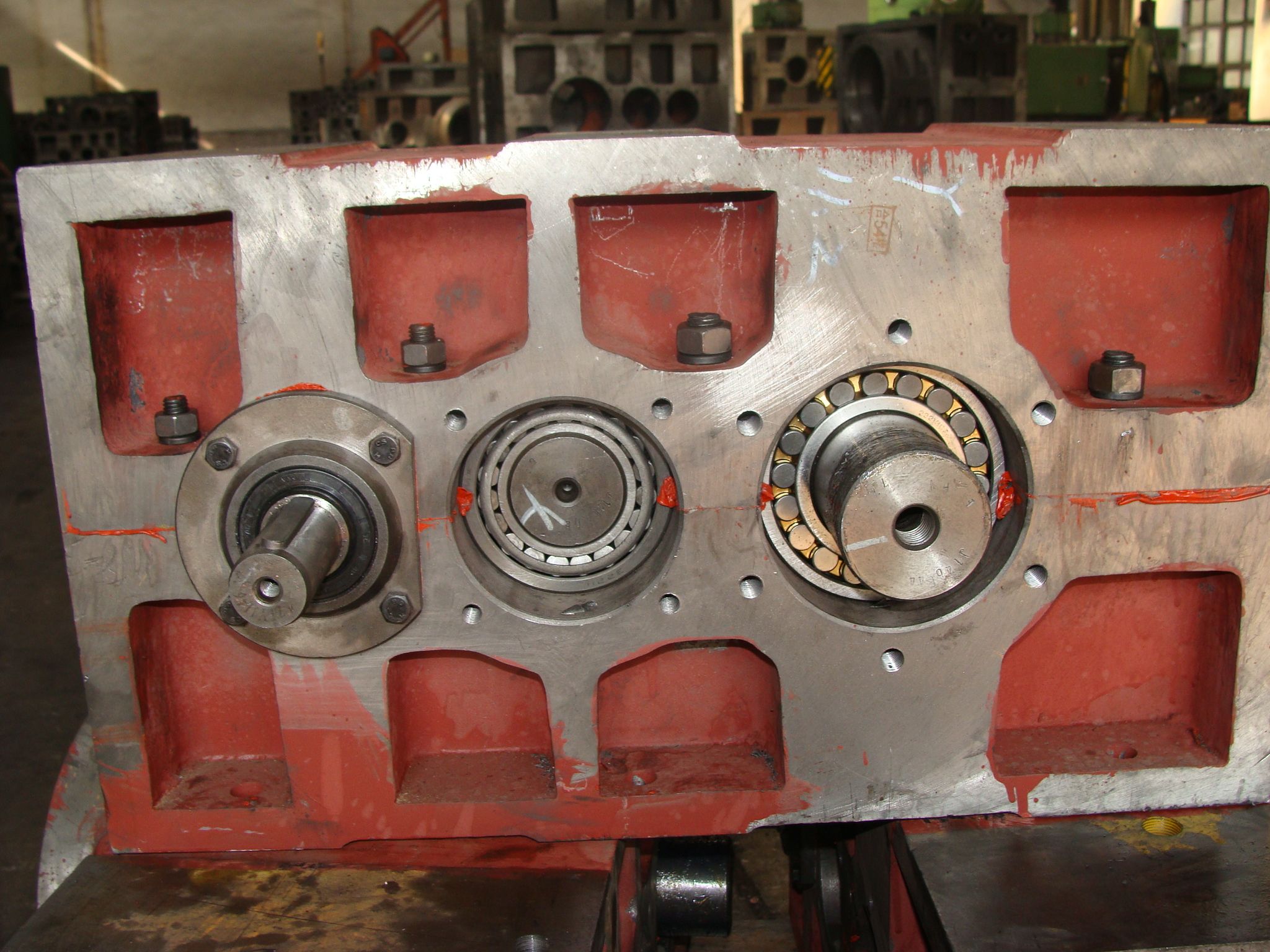
| Gear Type | Helical Gear |
| Weight (kg) | 17700.000000 |
| Ratio Range | 1 : 25…100 |
| Low Speed Output | Solid shaft without parallel key |
| Nominal Torque | 1030000 Nm |
| Mounting Arrangements | Horizontal mounting position |
| Manufacturer | WALTHER FLENDER GMBH |
| Country of Manufacture | Poland |
| Data Sheet & Drawings | Helical gear Reduction Box H3 flender extruder gearbox H3-CH26A |
Related Products