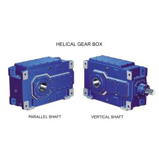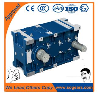

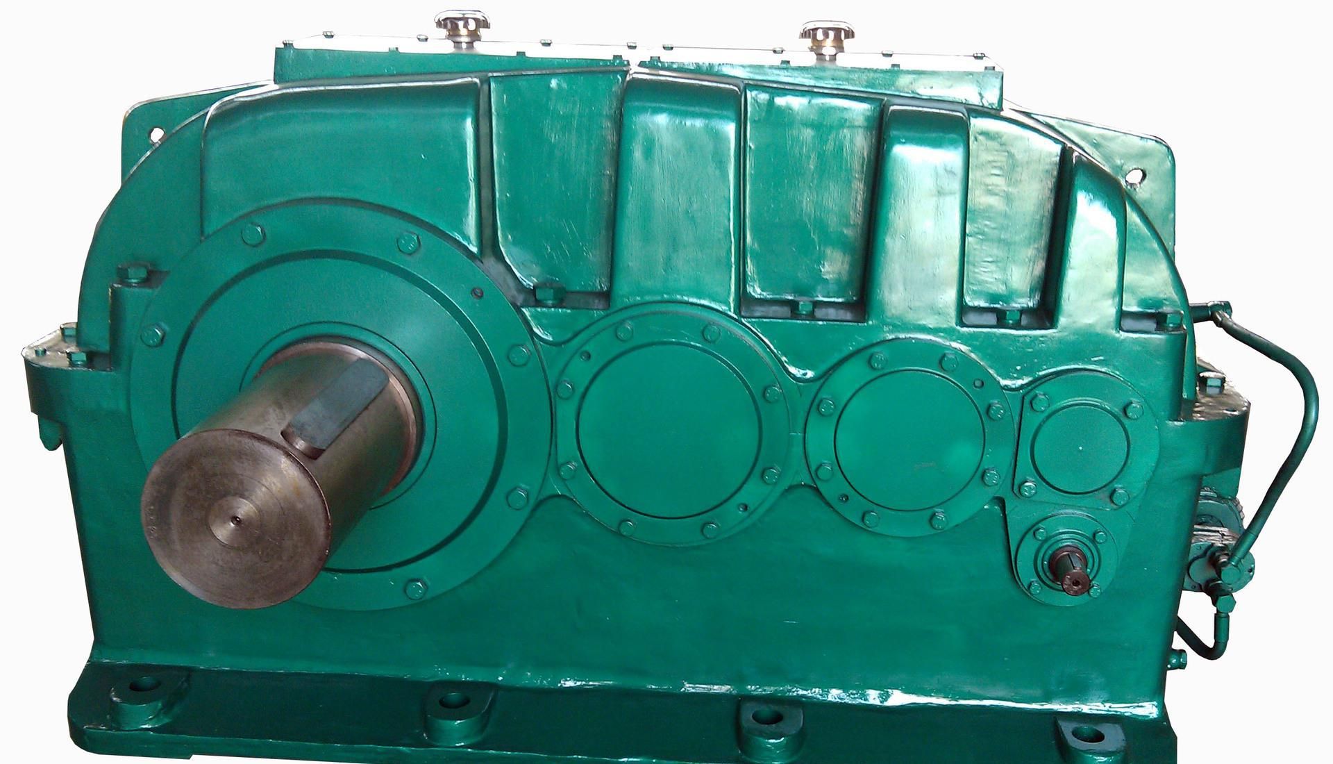
H2SV-17-C siemens flender gearbox catalogue pdf Helical gearboxes H2
In stock
SKU
H2SV-17-C
$99,642.86
Flender/Flender Gear Units/Helical gearboxes H2
0B G_MD3_XX_0 G8D8B G_MD3_XX_0 G8 G8D8 D8B G_MD3_XX_0 G8D8C G_MD3_XX_0 G8D8C G_MD3_XX_0G8D8C G8D8 G_MD3_XX_0C G_MD3_XX_0 G8 D8C G_MD3_XX_0D8 G8 G8 D8C G_MD3_XX_0 G8 D8D G_MD3_XX_0 G8 D8D G_MD3_XX_0G8 D8D G_MD3_XX_0D G8D8 G_MD3_XX_0 G8 D8D G_MD3_DE_0 G8 G8D8 D8D 1 G8D8E
  G_MD3_XX_0 G8D8 G_MD3_XX_0E 1G8D8 G_MD3_XX_0E G8 D8 G_MD3_XX_0E 1E G8D8 G_MD3_XX_0 3D8 G8 G8D8E G_MD3_XX_0 1 G8 D8 G_MD3_XX_0F G8
  D8F G_MD3_XX_0F 1 G8 D8 G_MD3_XX_0 G_MD3_XX_0F G8D8 1F G8 D8 G_MD3_XX_0 D8 G8 G8D8F G_MD3_XX_0 $Backstop, vertical mounting position
  only for H2, H3, H4 designs , , or B2 designs , , or B3 designs , , . %Backstop for type B4, gear unit sizes 5 and 5, vertical mounting position only for designs , , . &Backstop for type B4, gear unit sizes 5 to 5, vertical mounting position only for designs , , . Siemens AG 2 Options for operation Backstop 1/1 Siemens MD 3.1 2Overview Dimensions: Ordering information:Dimensions in mm Backstop Gear unit size H2 H3 H4 B2 B3 B4 D8 G8 D8 G8 D8 G8 D8 G8 D8 G8 D8 G8 5 1 2 5 1 2 2 3 1 2 5 1 2 1 2 2 3 1 2 1 2 5 1 2 1 2 2 3 1 2 1 2 5 1 3 1 2 1 2 2 3 1 2 1 2 5 1 3 1 2 1 2 2 3 1 2 1 2 5 2 3 2 3 1 2 2 4 1 3 1 2 5 2 3 2 3 1 2 2 4 1 3 1 2 5 2 3 2 3 1 3 2 3 1 3 5 2 3 2 3 1 3 2 3 1 3 5 3 4 2 4 1 4 2 4 1 4 5 3 4 2 4 1 4 2 4 1 4 Data position of Article No. 1 to 6 7Order code Article No.: 2LP2 .-.....-....- Backstop/direction of rotation Mounting of standard backstop, shaft d2 clockwise L0 Mounting of standard backstop, shaft d2 counter-clockwise L0 Preparation of gear unit for mounting standard backstop L0 Direction of rotation of shaft d2 with view on right stud L9 Direction of rotation of shaft d2 with view on left stud L9 Direction of rotation of shaft d2 with view on lower stud (vertical mounting position) L9 Direction of rotation of shaft d2 with view on upper stud (vertical mounting position) L9 Max. dimensions; details acc. to order-related documentation. Backstop not possible for: Type B
| Model Type | Helical gearboxes H2 |
|---|---|
| Gear Type | Helical Gear |
| Weight (kg) | 4650.000000 |
| Ratio Range | 1 : 6.3…20 |
| Low Speed Output | Solid shaft with parallel key acc. to DIN 6885/1 |
| Nominal Torque | 195000 Nm |
| Mounting Arrangements | Vertical mounting position |
| Manufacturer | Flender de Colombia |
| Country of Manufacture | China |
| Data Sheet & Drawings | H2SV-17-C siemens flender gearbox catalogue pdf Helical gearboxes H2 |
Related Products