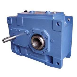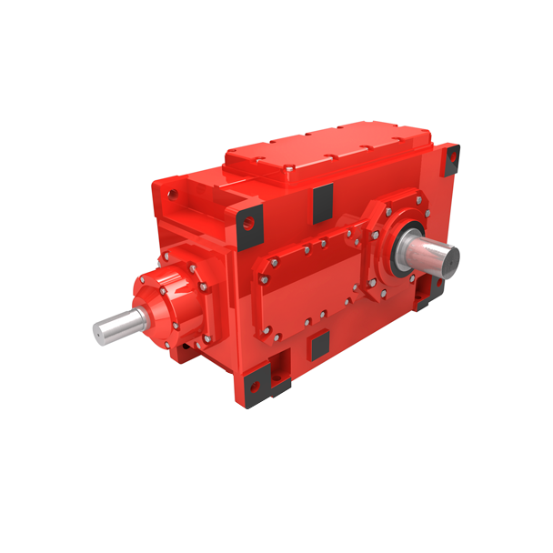
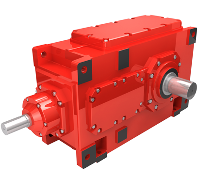
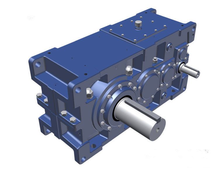

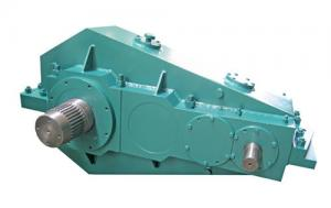
flender pty ltd H2DV-25-C Helical speed reducer H2
In stock
SKU
H2DV-25-C
$334,285.71
Flender/Flender Gear Units/Helical speed reducer H2
and PN 1.4 1 1 Check whether additional forces on the output shaft are permissible; see pages 1 and 1 1.5 3 Check whether the actual ratio as per tables on page 3 is acceptable 3.1 Adequate for gear units
  without auxiliary cooling, if: 3.2 Gear units with fan cooling on request 3.3 For higher thermal capacities, cooling by external
  oil cooler on request 1. Determination of gear unit typeand size 3.3 2 PN Horizontal mounting position 2. Determination of
  oil supply All parts to be lubricated are lying in the oil or are splash lubricated. Forced lubrication on request 3. PG Determination of required thermal capacity PGPN P2 f1x f2 PN TA n1 f3 9is = n1 n2 Helical Gear Units With Extended Total Centre Distance Guidelines for the Selection Siemens MD K2-1 2/2 ED = % ED = 8% / ) f1 = 2 1 f2 = 9 f3 = 2 1 f4 = 3 1 f6 = 4 1 f8 = 5 1 f9 = 6 1 = iN = is = n1 = 1/min n2 = 1/min PG = PG1 = 1 PN = kW 1 1 P2 = kW = TA = Nm T2N = kNm 1 Key to symbols: ED = Operating cycle per hour in %, .. ED = 8% / f1 = Factor for driven machine (table , page 1 f2 = Factor for prime mover, page 9 f3 = Peak torque factor (table , page 1 f4 = Thermal factors (table , page 1 f6 = Factor for altitude (table , page 1 f8 = Oil supply factor (table , page 1 f9 = Thermal capacity factor (table , page 1 = Actual ratioi = Nominal ratio is = Required ratio n1 = Input speed (1/min) n2 = Output speed (1/min) PG = Required thermal capacity PG1 = Thermal capacity for gear units without auxiliary cooling, page 1 PN = Nominal power rating of gear unit (kW), see rating tables page 1 and 1 P2 = Power rating of driven machine (kW) = Ambient temperature () TA = Max. torque occurring on input shaft, .. peak operating-, starting- or braking torque (Nm) T2N = Nominal output torque (kNm), page 1Helical Gear Units With Ex
| Model Type | Helical speed reducer H2 |
|---|---|
| Gear Type | Helical Gear |
| Weight (kg) | 15600.000000 |
| Ratio Range | 1 : 6.3…20 |
| Low Speed Output | Hollow shaft with shrink disk |
| Nominal Torque | 860000 Nm |
| Mounting Arrangements | Vertical mounting position |
| Manufacturer | Flender Oy |
| Country of Manufacture | Egypt |
| Data Sheet & Drawings | flender pty ltd H2DV-25-C Helical speed reducer H2 |
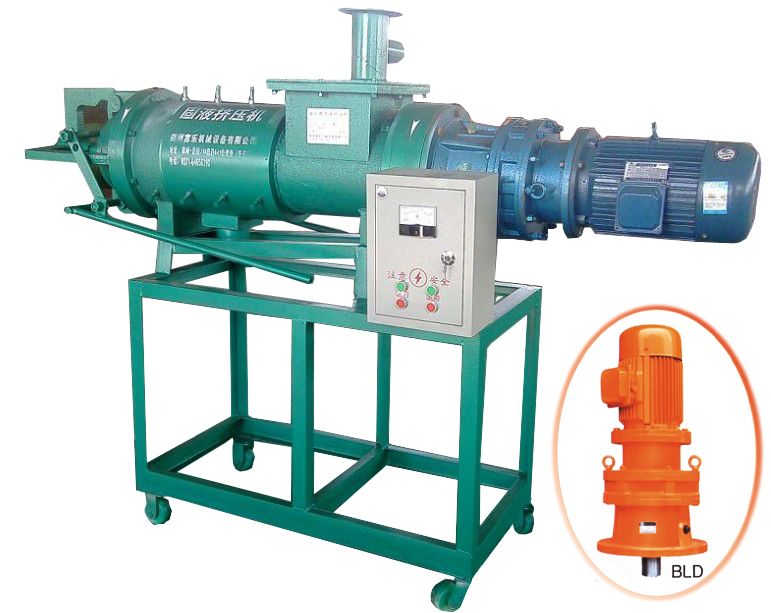
Related Products