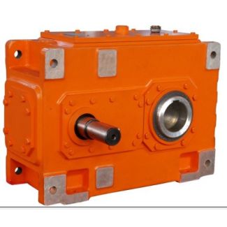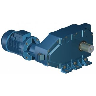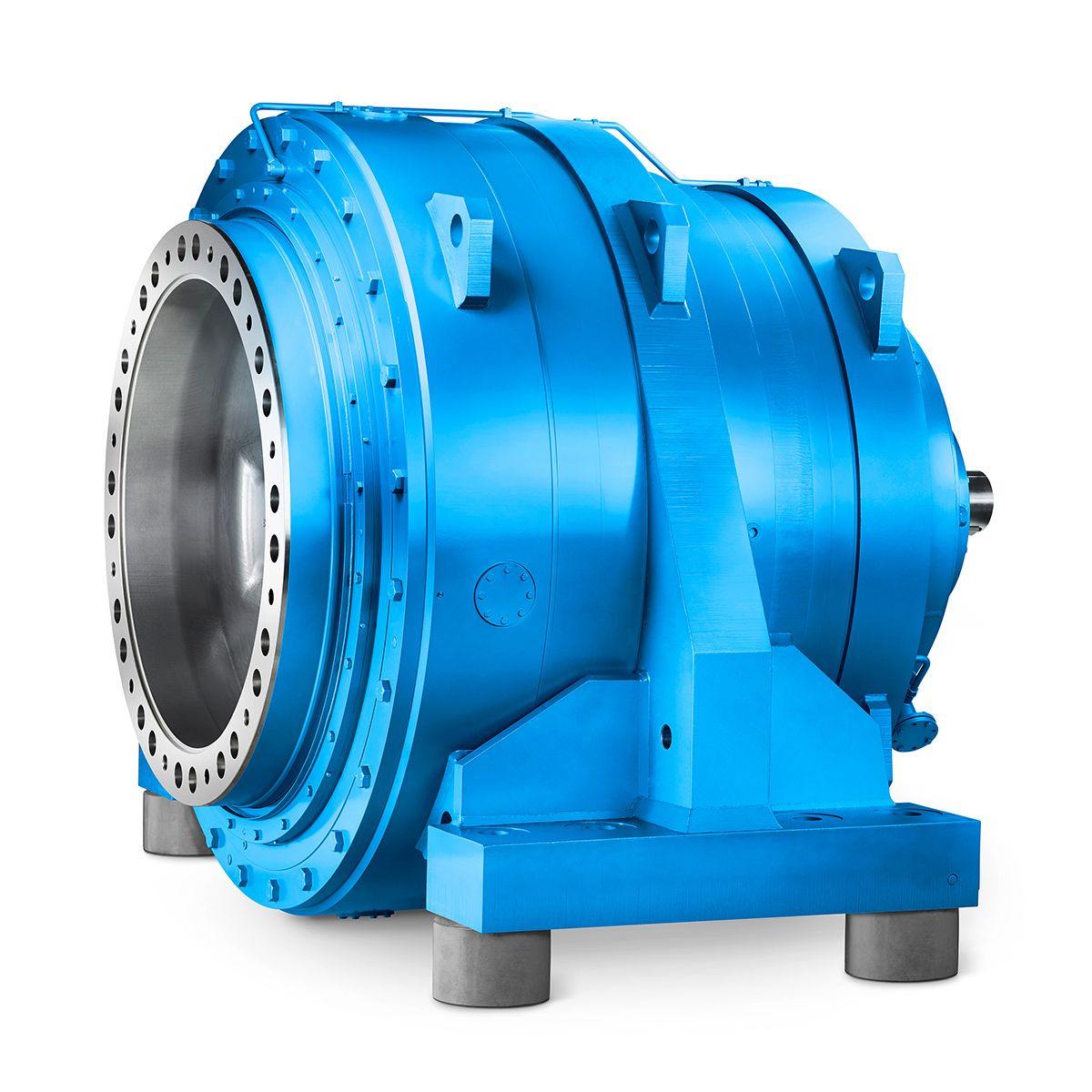


flender graffenstaden s a s H2DH-20-C Helical gear Reduction Box H2
In stock
SKU
H2DH-20-C
$160,714.29
Flender/Flender Gear Units/Helical gear Reduction Box H2
ak torque factor (table , page 1 f4 = Thermal factor (table , page 1 f6 = Factor for altitude (table , page 1 f8 = Oil supply factor (table , page 1 = Actual ratio iN = Nominal ratio
  is = Required ratio n1= Input speed (min- n2= Output speed (min- PG= Required thermal capacity PGA= Thermal capacity for
  gear units without auxiliary cooling, pages 1 - 1 PGB= Thermal capacity for gear units with fan,pages 1 - 2
  = Nominal power rating of gear unit (kW), see rating tables,pages 1 and 1 2= Power rating of driven machine (kW) = Ambient temperature ( ) TA= Max. torque occurring on input shaft, .. peak operating, starting orbraking torque (Nm) 2N= Nominal output torque (kNm) page 2Explication des symboles: ED= Dure dutilisation en , par ex: (ED = 8 par heure) f1 = Facteur de travail des machines (tableau , page 1 f2 = Facteur des machines motrices (tableau , page 1 f3 = Facteur des pointes maximales (tableau , page 1 f4 = Facteur thermiques (tableau , page 1 f6 = Facteur daltitude (tableau , page 1 f8 = Facteur dalimentation en huile (tableau , page 1 = Rapport rels iN = Rapport nominaux is = Rapport thoriques n1= Vitesse dentre (min- n2= Vitesse de sortie (min- PG= Capacit thermique ncessaire PGA= Capacit thermique limite sans systme de refroidissement compl- mentaire, pages 1 - 1 PGB Capacit thermique limite pourrducteurs avec ventilateur,pages 1 - 2 = Puissance nominale du rducteur (kW); voir tableaux de puissance,pages 1 et 1 2= Puissance de la machine de travail (kW) = Temprature ambiante ( ) TA= Couple maximal larbre dentre; par ex: pointes de fonctionnement,couple de freinage ou de dmarrage (Nm) 2N= Couple nominal de sortie (kNm) page 2 P2q = quivalente Leistung (kW) PI, PII, Pn = Leistungsanteile (kW) aus Lastkollektiv XI, XII, Xn = Zeitanteile (%) aus LastkollektivP2q = Equivalent power rating (kW) PI, PII, Pn = Fractions of power rating (kW) obtained from service classification XI, XII, Xn = Fractions of time (%) obtained fro
| Model Type | Helical gear Reduction Box H2 |
|---|---|
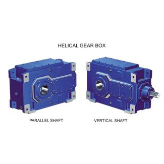
| Gear Type | Helical Gear |
| Weight (kg) | 7500.000000 |
| Ratio Range | 1 : 7.1…22.8 |
| Low Speed Output | Hollow shaft with shrink disk |
| Nominal Torque | 335000 Nm |
| Mounting Arrangements | Horizontal mounting position |
| Manufacturer | Beijing Flender |
| Country of Manufacture | Liechtenstein |
| Data Sheet & Drawings | flender graffenstaden s a s H2DH-20-C Helical gear Reduction Box H2 |
Related Products