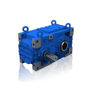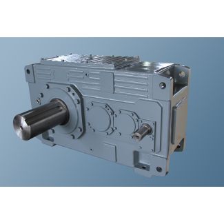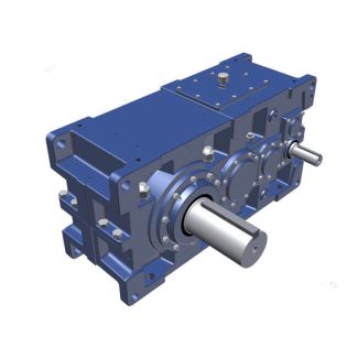

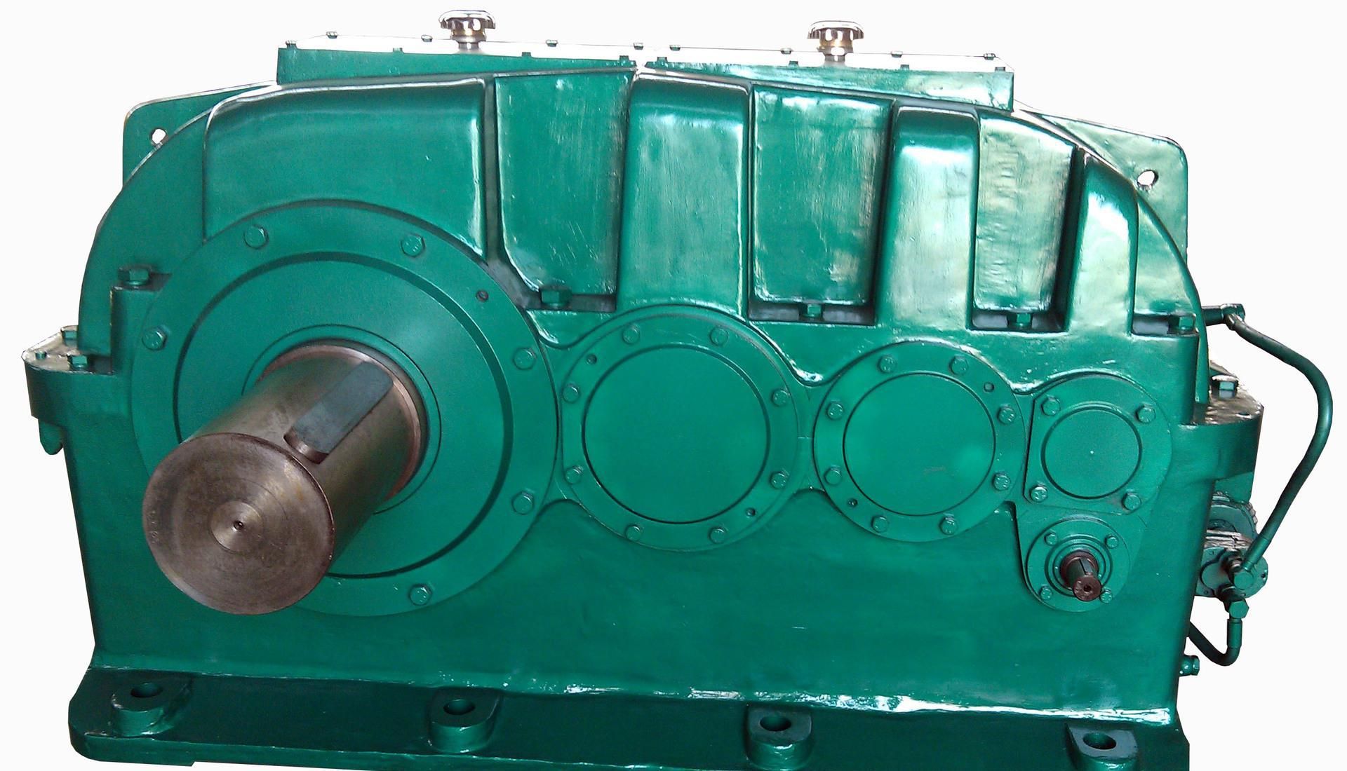
H2-SV-20-D flender gearbox indonesia Helical gear units H2
In stock
SKU
H2-SV-20-D
$160,714.29
Flender/Flender Gear Units/Helical gear units H2
1 f6,f7=Factors for altitude (tables 6 + , page 1 f8=Oil supply factor for vertical gear units (table , page 1. For horizontal gear units: 8 = 1 f9, f1 f1, f1=Thermal capacity factors (tables 9 ... , pages 1
  + 1 a1=Size factor a2=Transmission ratio factor = Actual ratio iN=Nominal ratio is=Required ratio n1=Input speed (1/min) n2=Output speed (1/min)
  PG=Required thermal capacity PG1=Thermal capacity for gear units without auxiliary cooling, pages 2 - 2 PG2=Thermal capacity for gear units
  with fan cooling, pages 2 - 2 PG3=Thermal capacity for gear units with built-in cooling coil, pages 2 - 2 PG4=Thermal capacity for gear units with built-in cooling coil and fan, pages 2 - 2 PN=Nominal power rating of gear unit (kW), see rating tables, pages 2 - 2 P2=Power rating of driven machine (kW) = Ambient temperature ( ) TA=Max. torque occurring on input shaft, .. peak operating-, starting- or brak- ing torque (Nm) T2N=Nominal output torque (kNm), pages 3 - 3Explication des symboles: ED=Dure dutilisation en %, par ex: (ED = 8 % par heure) f1=Facteur de travail des machines (tableau , page 1 f2=Facteur des machines motrices (tableau , page 1 f3=Facteur des pointes maximales (tableau , page 1 f4, f5=Facteurs thermiques (tableau 4 + , page 1 f6,f7=Facteurs daltitude (tableau 6 et , page 1 f8=Facteur dalimentation en huile pour les reducteurs verticaux (tableau , page 1. Pour les reducteurs horizontaux: 8= 1 f9, f1 f1, f1=Facteurs thermiques limites (tableau 9 ... , pages 1 + 1 a1=Facteur de taille a2=Facteur de rapport = Rapport rel iN=Rapport nominal is=Rapport thorique n1=Vitesse dentre (1/min) n2=Vitesse de sortie (1/min) PG=Capacit thermique ncessaire PG1=Capacit thermique limite sans systme de refroidissement compl- mentaire, pages 2 - 2 PG2Capacit thermique limite pour rduc- teurs avec refroidissement par ventila- teur, pages 2 - 2 PG3=Capacit thermique limite pour rduc- teurs avec serpentin de refroidisse- ment, pages 2 - 2 PG4=Capacit thermique
| Model Type | Helical gear units H2 |
|---|---|
| Gear Type | Helical Gear |
| Weight (kg) | 7500.000000 |
| Ratio Range | 1 : 7.1…22.8 |
| Low Speed Output | Solid shaft with parallel key acc. to DIN 6885/1 |
| Nominal Torque | 335000 Nm |
| Mounting Arrangements | Vertical mounting position |
| Manufacturer | Flender..Ltd China(Tianjin) |
| Country of Manufacture | China |
| Data Sheet & Drawings | H2-SV-20-D flender gearbox indonesia Helical gear units H2 |
Related Products