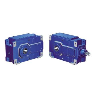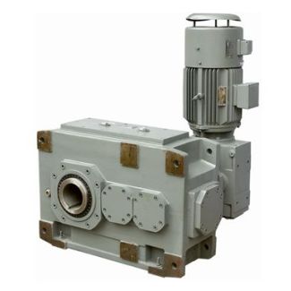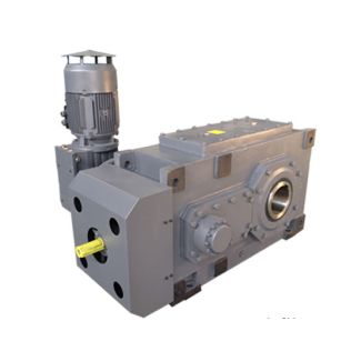
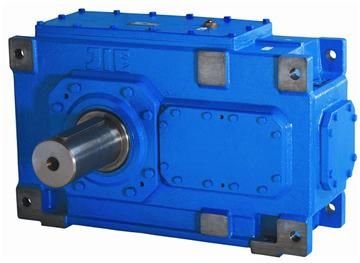
H2-FV-21-A flender siemens Helical gear reducers H2
In stock
SKU
H2-FV-21-A
$190,714.29
Flender/Flender Gear Units/Helical gear reducers H2
bles 3/1 Type H1 3/2 Type H2 3/2 Type H3 3/3 Type H4 3/3 Type B2 3/5 Type B3 3/5 Type B4 3/6 Types H1, H2, H3, H4 Moments of inertia J1 3/6 Types B2, B3, B4 Moments of inertia
  J1 3/6 Types H1, H2, H3, H4 Actual ratio 3/6 Types B2, B3, B4 Actual ratio Design of the gear
  units Siemens AG 2 Design of the gear units Guidelines for selection Constant mechanic al power rating 3/2 Siemens MD
  3.1 2Overview 1. Determination of gear unit type and size 1.1.Find the transmission ratio 1.2.Determine the nominal power rating of the gear unit It is not necessary to consult us, if: 1.3 Check for maximum torque ..: peak operating, starting or braking torque Gear unit sizes and number of reduction stages are given in rating tables depending on iN and P2N. 1.4 Check whether additional forces on the output shaft are permissible; it is essential to consult Siemens! 1.5 Check whether the actual ratio as per tables on pages 3/6 to 3/6 is acceptable.2. Determination of oil supply: Horizontal mounting position () Dip lubrication (all parts to be lubricated are immersed in the oil or are splash lubricated) Oil circulation lubrication by means of flange-mounted pump (type H1 only) Vertical mounting position () Dip lubrication with oil expansion unit Forced lubrication on request Upright mounting positions (, ) Dip lubrication with oil expansion unit Forced lubrication on requestn1 n2is = P2N P2 f1 f2 P2 P2N 3.3 TA n1 9P2N f3 Siemens AG 2 Design of the gear units Guidelines for selection Constant mechanical power rating 3/3 Siemens MD 3.1 2Overview (continued) 3. Determination of required thermal capacity PG Assumptions deviating from operating conditions f8 = .........(see pages 3/1 - 3/ PGD1 = ......... f5 = ......... Gear unit withfan andcooling coilis sufficient Water-/ air-oil cooler Variation of the following items is possible:Please consult the sales person responsibleP < 2 G_MD3_EN_0c The type of the possibly required auxili
| Model Type | Helical gear reducers H2 |
|---|---|
| Gear Type | Helical Gear |
| Weight (kg) | 8900.000000 |
| Ratio Range | 1 : 7.1…20 |
| Low Speed Output | Flanged shaft |
| Nominal Torque | 410000 Nm |
| Mounting Arrangements | Vertical mounting position |
| Manufacturer | A. Friedr. Flender GmbH |
| Country of Manufacture | Panama |
| Data Sheet & Drawings | H2-FV-21-A flender siemens Helical gear reducers H2 |
Related Products