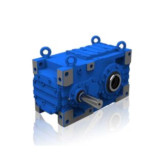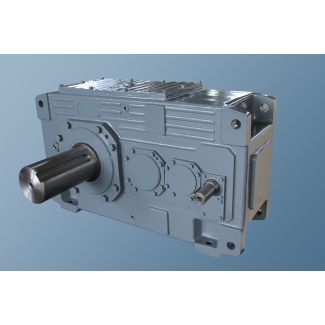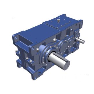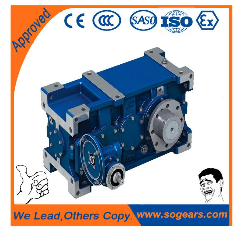

H2-FH-26B flender atb loher antriebstechnik ag Helical speed reducers H2
In stock
SKU
H2-FH-26B
$375,000.00
Flender/Flender Gear Units/Helical speed reducers H2
Basic data known from previous gear sets or other experience should form the basis of the draft design. Outer pitch diameter e2The outer pitch diameter determines the size of the gear unit. The available installation space is usually also determined
  in the specica-tions. The necessary pitch diameter depends on the transmitted torque, the trans-mission ratio and the material employed. Springer-Verlag
  Berlin Heidelberg 2 . Klingelnberg (ed.), Bevel Gear , DOI 1.1/9-3-6-4-0_3 In [NIEM8.3 ], it is suggested that on the
  basis of known designs, factor * should be determined by means of the respective virtual cylindrical gear data. Thisfactor should be used to calculate the outer pitch diameter of the pinion, employing the following draft formula: e1 1 /C1T1 /C1K/C3 K3s 3:2 /C3 KFmt b1/C1dv1/C1/C1 /C1uv1 uv/C1/C1 3:3 If no empirical values exist, Eq. 3.4according to [ KN3 ] supplies good working values for design on the safe side. de2 1/C1T1/C1u3 u2/C1/C1 /C1n1p 2;8s 3:4 Face width When choosing the face width, it has proved useful to keep to certain size relationships. Two criteria may be employed: The ratio of the outer cone distance of the wheel to its face width should meet the condition below: (3.0/C2Re2/b2/C2.0) and the ratio of the face width of the wheel to the mean normal module should meet the following condition: (7.0/C2b2/mmn/C2.0). The rst criterion is useful only for bevel gears with shaft angle of roughly 9/C1; in other cases, the criterion for 2/mmnshould be satised since, otherwise, the teeth will be too wide. Number of teeth Several criteria need to be considered when choosing the number of teeth for the pinion and wheel. The number of teeth will inuence not only the prole curvature and the whole depth but also usability in terms of undercutting and pointed teeth. As is known from cylindrical gears, the proleshift needed to avoid undercutting will decrease with higher tooth numbers if thetransmission ratio is kept constant. Various approaches ar
| Model Type | Helical speed reducers H2 |
|---|---|
| Gear Type | Helical Gear |
| Weight (kg) | 17500.000000 |
| Ratio Range | 1 : 7.1…22.4 |
| Low Speed Output | Flanged shaft |
| Nominal Torque | 1030000 Nm |
| Mounting Arrangements | Horizontal mounting position |
| Manufacturer | Siemens AG |
| Country of Manufacture | Chile |
| Data Sheet & Drawings | H2-FH-26B flender atb loher antriebstechnik ag Helical speed reducers H2 |
Related Products