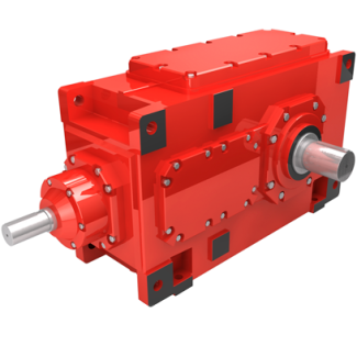


Flender/Flender Gear Units/Helical gearboxes H2
alculation of stress correction factor Sa Designation Formula No. Stress correction factor YSaD,C1:2:1LaD, /C1 qsD,C1=1:2:3=LaD, /C1/C1(4. where: LaD,CsFn hFaD,CandqsD,CsFn 2FD,(4. Table 4.9 Calculation of contact ratio factor Designation Formula No. Contact ratio factor For v0: Y0:2:7 /C2:6(4. For 0 <<1:
  Y0:2:7 v0:7 :3/C1/C1 /C2:6(4. Forv>1: Y0:6(4. Fig. 4.1 Zone of action to calculate load sharing according to [ FVA4 ]4.2
  Load Capacity Calculation 1 In accordance with ISO1 Method B1, parabolic peak load distribution ais assumed to prevail along the
  line of action. The load distribution balong contact lineccorresponds to semi-ellipse (Fig. 4.. The major axis of the ellipse of Hertzian pressure is taken to be the contact line. Fig. 4.1 Peak load distribution over the zone of action and load distribution over the contact lines Table 4.1 Calculation of load sharing factor LSfor zone of action in the shape of parallelogram Designation Formula No. Face load factorYLSAm AtAmAr(4. where: Aarea of the semi-ellipse over contact line At,Am,Arcalculated using ,fm,fracc. to Table 4.1 Area of semi- ellipse over contact lineA1 4p/C3lb(4. Peak load dis- tribution along the path of contactp/C3p pmax1fjj fmaxjj/C1/C1e where: e1.5 for high crowning (.., industry applications) e3.0 for low crowning (.., automotive applications)(4. where: fmaxthe larger value of max0 and maxb(4. fmax0 2gvbvefftantanvb /C1 /C1cosvb(4. fmaxb1 2gvbvefftantanvb /C1 /C1cosvb(4. arctantan0 cosvet/C1/C1(4. bveffandaccording to Table 4.4 Length of the contact line lblb0 1f fmax/C1/C1 ! 1 bveff bvr/C1/C1 2vuut(4. (continued)1 4 Load Capacity and Efciency Bevel spiral angle factor BSThe bevel spiral angle factor BSfor bending stress considers contact lines shorter than the face width because of their inclination(Table 4..Table 4.1 (continued) Designation Formula No. Theoretical length of thecontact linel b0 x1x2 2y1y2 2q(4. Parameter
| Model Type | Helical gearboxes H2 |
|---|---|
| Gear Type | Helical Gear |
| Weight (kg) | 25000.000000 |
| Ratio Range | 1 : 9…22.4 |
| Low Speed Output | Hollow shaft with shrink disk |
| Nominal Torque | 1400000 Nm |
| Mounting Arrangements | Horizontal mounting position |
| Manufacturer | Flender Ges.m.b.H. |
| Country of Manufacture | Peru |
| Data Sheet & Drawings | flender penig H2-DH28A Helical gearboxes H2 |
Related Products