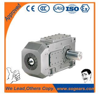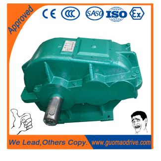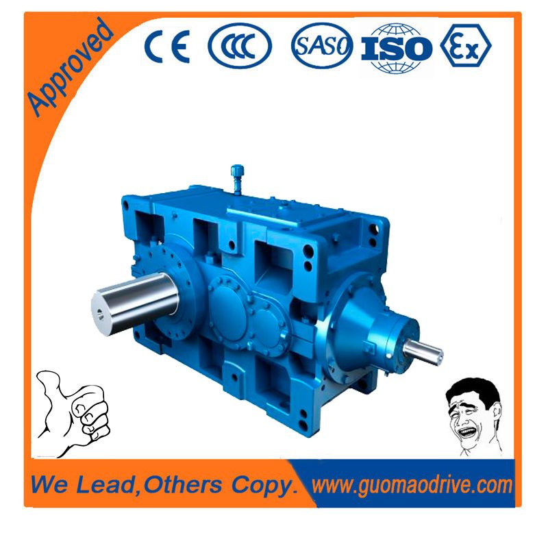
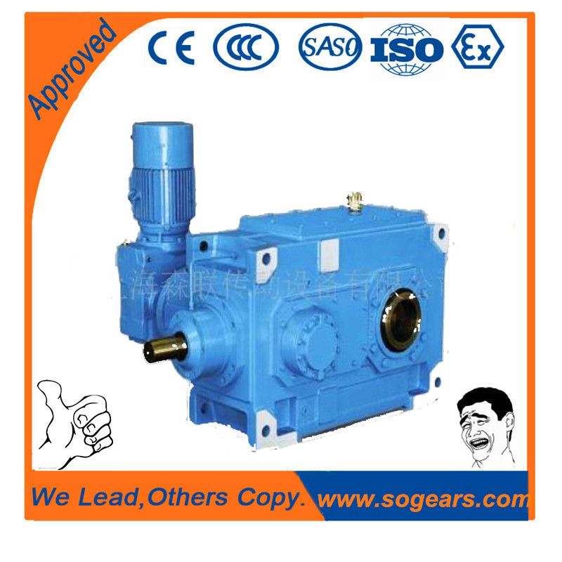


flender pin bush coupling catalogue H2-DH-26-D Helical gear reducer H2
In stock
SKU
H2-DH-26-D
$375,000.00
Flender/Flender Gear Units/Helical gear reducer H2
al that this peak was nota synchronous vibration and occurred at half shaft frequency. In case of startup without trip, cascade spectra were recorded up to maximum speed. It appeared (Figure 8 and Figure that thevibration peaks were maximum for
  compressor speed ofapproximately 8 rpm. better analysis of the cascade plotsduring the startup indicated natural mode of vibration at thisfrequency,
  which could explain that the peak of vibration was dueto mechanical structure resonance and not to bearing instability. Figure 8.
  Cascade on HS DE Side for and -Ways During Cold Startup. Figure 9. Cascade on HS DE Side for and -Ways During Hot Startup.PROCEEDINGS OF THE 3TH TURBOMACHINERY SYMPOSIUM 9 MAINTENANCE AND ONLINE DIAGNOSTICS ON GEARBOXES IN THE PETROCHEMICAL INDUSTRY 9 We observed two important phenomena on cascade records: Resonance appeared only on one probe (-way) Excitation frequency was not fluid instability but low-speed shaft frequency at 0.4 times the HS shaft frequency (= 1/2. Progress was made with these different measurements, which led to coherent explanation. One vibration probe holder wassuspected of having resonance mode of vibration during startup. Variation of resonance response during startup was not due to the thermal unbalance on the high-speed shaft, but on thelow-speed shaft. Vibrations at low speed frequency weretransmitted to the probe holder through the casing. The intensityof this excitation was function of the initial thermal unbalanceon the shafts. Investigations of the drawings confirmed that the probe holder sleeve on the DE -way was designed longer than the three othersinstalled on the HS gearbox shaft, and could have lateral mode of vibration at frequency around 6 Hz. The compressor units were on duty for gas reinjection, and it was very difficult to schedule special tests, modifications, orrepetitive startups. During one short stop of the unit, it was possibleto modify the -way probe holder in order to increase its lat
| Model Type | Helical gear reducer H2 |
|---|---|
| Gear Type | Helical Gear |
| Weight (kg) | 17500.000000 |
| Ratio Range | 1 : 7.1…22.4 |
| Low Speed Output | Hollow shaft with shrink disk |
| Nominal Torque | 1030000 Nm |
| Mounting Arrangements | Horizontal mounting position |
| Manufacturer | Siemens AG |
| Country of Manufacture | Palau |
| Data Sheet & Drawings | flender pin bush coupling catalogue H2-DH-26-D Helical gear reducer H2 |
Related Products