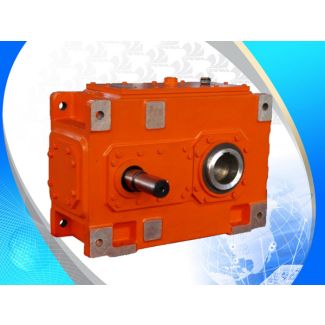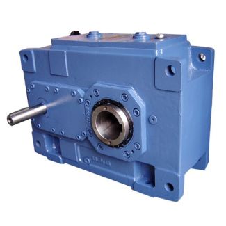
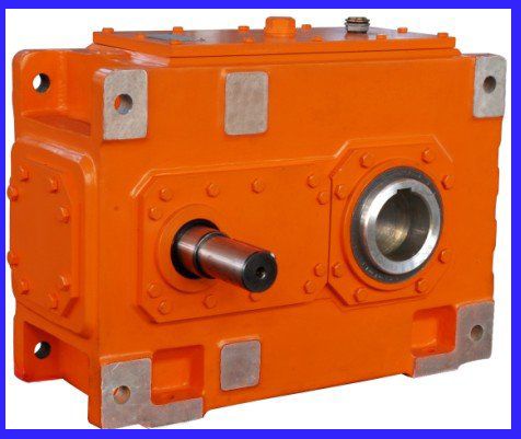


flender stahl H2-DH-22B Helical gear Reduction Boxes H2
In stock
SKU
H2-DH-22B
$205,714.29
Flender/Flender Gear Units/Helical gear Reduction Boxes H2
al Centre Distance Service Factors for Crane Installations 2 Table 2 f1 f3 Factor for driven machine f1, peak torque factor f3 / Loads Service factors / Classes of utilization of mechanism States of loading of mechanism De nitionsT 0
  1 2 3 4 5 6 7 8 9 / Service life in hours > 2 > 4 > 8
  > 1,6 > 3,2 > 6,3 > 1,5 > 2,0 > 5,0 2 4 8 1,6 3,2 6,3 1,5 2,0
  5,0 light L1 Max. load only exceptionally, but only very low loads continuouslyk 0,5f1 2f3 3f3.0 0.5.8M1.0 0.5.8M1.0 0.5.8M1.0 0.5.8M2.0 0.5.8M3.1 0.5.8M4.1 0.5.8M5.2 0.6.9M6.2 0.7.0M7.3 0.8.1M8 medium L2 Max. load quite often, but low loads continuousy0,5 < 0,6f1 2f3 3f3.0 0.5.8M1.0 0.5.8M1.0 0.5.8M2.0 0.5.8M3.1 0.5.8M4.1 0.5.8M5.2 0.5.8M6.2 0.6.9M7.3 0.7.0M8.4 0.8.1M8 heavy L3 Max. load frequently and medium loads continuously0,6 < 0,8f1 2f3 3f3.0 0.5.8M1.0 0.5.8M2.0 0.5.8M3.1 0.5.8M4.1 0.5.8M5.2 0.5.8M6.2 0.6.9M7.3 0.7.0M8.4 0.8.1M8.6 0.9.2M8 very heavy Loads regularly nearest to max. load0,8 < 1,0f1 2f3 3f3.0 0.5.8M2.0 0.5.8M3.1 0.5.8M4.1 0.5.8M5.2 0.5.8M6.3 0.5.8M7.4 0.6.9M8.6 0.7.0M8.8 0.8.1M8.0 0.9.2M8 f1 = Factor for driven machine f3 = Peak torque factor for constant load direction, as rule for hoisting gears, luf ng gears, etc. f3 = Peak torque factor for alternating load direction, as rule for slewing gears, travelling gears, etc. Group classi cation of mechanism , = 3 km (km = nominal load spectrum factor, see FEM 1.0, booklet 2, pages 2 - . Groups of mechanism M1 to M8 determined acc. to FEM 1.0, 3rd issue, f2 = 1.0 (drive via electric or hydraulic motor). If no max. torque has been stated, 2max = 1.6 T2 has to be determined. f1 = f3 = f3 = kk = 3 kmkm FEM1.0 2 2 - 9 M1 M8 FEM1.0 3. f2 = 1.0 T2max = 1.6T2 1L4 Group classi cation of mechanism 4 4 Siemens MD K2-1 2/2Helical Gear Units With Extended Tot
| Model Type | Helical gear Reduction Boxes H2 |
|---|---|
| Gear Type | Helical Gear |
| Weight (kg) | 9600.000000 |
| Ratio Range | 1 : 8…22.4 |
| Low Speed Output | Hollow shaft with shrink disk |
| Nominal Torque | 458000 Nm |
| Mounting Arrangements | Horizontal mounting position |
| Manufacturer | Flender GmbH |
| Country of Manufacture | Mexico |
| Data Sheet & Drawings | flender stahl H2-DH-22B Helical gear Reduction Boxes H2 |
Related Products