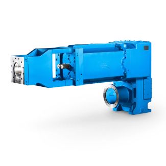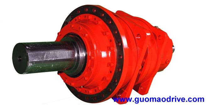
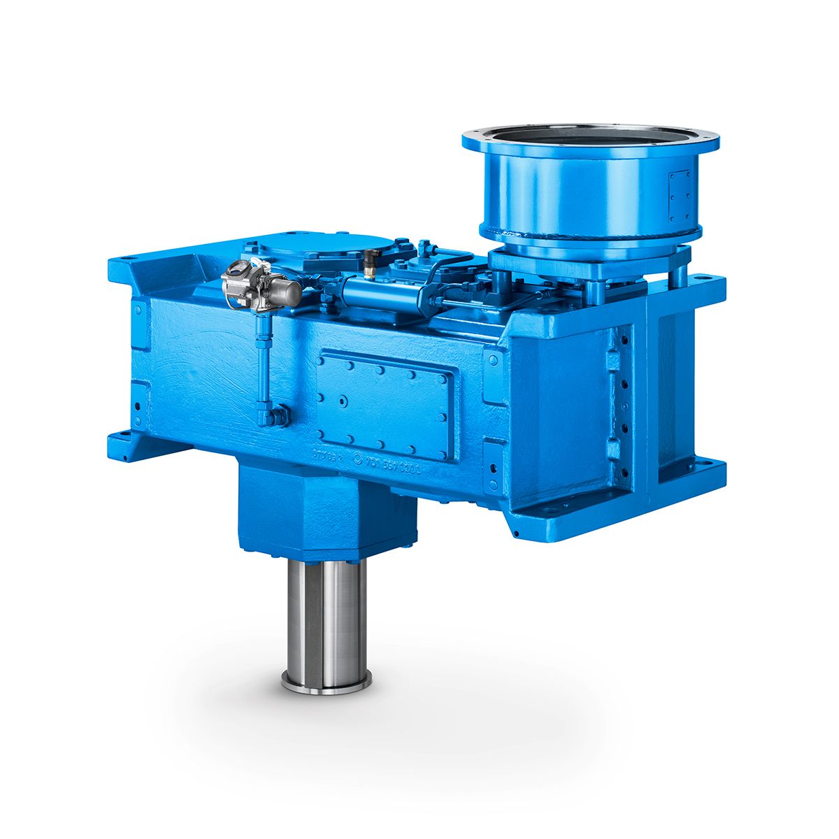
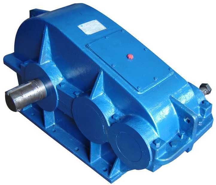

Flender/Flender Gear Units/Helical gear reducers H2
2S., designs , , , and type B2D., designs and . This option applies to gear units with shaft d2 at both ends. Siemens AG 2 Options for operation Oil level indicator, housing material, oil drain valve, breather 1/1 Siemens
  MD 3.1 2Overview Oil level indicator For checking the oil level, FLENDER SIG gear units are equipped with dipstick. An
  oil sight glass or oil level indicator of type FSA 1 can also be ordered. Oil level indicator type FSA
  1 cannot be installed in conjunc-tion with labyrinth seal. Housing material Cast iron is the housing material used as standard. As an alternative, welded housings can be ordered. Oil drain valve FLENDER SIG gear units are supplied with an oil drain screw with permanent magnet. As an alternative, oil drain valves can be ordered in various designs. For gear units with an oil drain valve, it is possible to order an additional screw plug with permanent magnet in the oil sump depending on the selection of other options, selection via .CAT NG. Gear unit ventilation In order to equalize pressure differences between the gear unit in- terior and the ambient atmosphere, FLENDER SIG are equipped as standard with an air filter suitable for use in environments where dust and water spray are present. Air filters for other kinds of ambient conditions can also be ordered.Data position of Article No. 1 to 6 7Order code Article No.: 2LP2 .-.....-....- Oil level indicator Oil sight glass H5 Oil level indicator of type FSA 1 H5 Data position of Article No. 1 to 6 7Order code Article No.: 2LP2 .-.....-....- Housing material Steel (welded) K2 Data position of Article No. 1 to 6 7Order code Article No.: 2LP2 .-.....-....- Oil drain Gear unit in mounting position "": Oil drain valve on gear unit face 4, straight design Gear unit in mounting position "": Oil drain valve on gear unit face 4, straight designGear unit in mounting position "": Oil drain valve on gear unit face 2, straight designK3 Gear unit in mounting position "":
| Model Type | Helical gear reducers H2 |
|---|---|
| Gear Type | Helical Gear |
| Weight (kg) | 960.000000 |
| Ratio Range | 1 : 8…28 |
| Low Speed Output | Solid shaft without parallel key |
| Nominal Torque | 42200 Nm |
| Mounting Arrangements | Horizontal mounting position |
| Manufacturer | Flender Macneill Gears Ltd. |
| Country of Manufacture | Russia |
| Data Sheet & Drawings | H2-CH10A flender gear box Helical gear reducers H2 |
Related Products