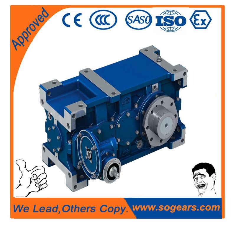
Helical gearboxes H2 graffenstaden flender H2-CH-27-A
In stock
SKU
H2-CH-27-A
$471,428.57
Flender/Flender Gear Units/Helical gearboxes H2
3/1 ...3/6 Designation of gear unit faces ...................... 1/3 Dimensions of oil expansion unit B2, B3, B4, upright mounting position, output at bottom ....................... 9/1 B2, B3, B4, vertical mounting position ................................................... 8/1 H1, H2, H3, H4, upright mounting position,
  output at bottom ....................... 6/2 H1, H2, H3, H4, vertical mounting position ................................................... 5/1 Dip lubrication ............................................... 2/2 Direction of
  rotation ........................1/1 , 1/3E Explanation of symbols used in the dimensional drawings ...................................1/4 Explosion protection as per ATEX 9 .........................................
  1/2 , 1/2 Externally mounted parts Options for ...............................1/1 ...1/3 Factory certificates ....................................1/3 Fan ..............................................................1/6 Fitting dimensions for IEC motors ..................................1/2 ...1/3 Flange dimensions for IEC motors .................................................1/2 Flange-mounted pump ................................1/5 Further information ....................................1/3 Gear unit designations ..................................1/2 Gear unit dimensions Type B2, horizontal mounting position ..........................................7/2 ...7/5 Type B2, upright mounting position, output at bottom ..............9/2 ...9/5 Type B2, vertical mounting position ..........................................8/2 ...8/5 Type B3, horizontal mounting position ........................................7/6 ...7/1 Type B3, upright mounting position, output at bottom ............9/6 ...9/1 Type B3, vertical mounting position ..........................................8/6 ...8/7 Type B4, horizontal mounting position ......................................7/1 ...7/1
| Model Type | Helical gearboxes H2 |
|---|---|
| Gear Type | Helical Gear |
| Weight (kg) | 22000.000000 |
| Ratio Range | 1 : 8…20 |
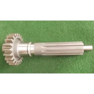
| Low Speed Output | Solid shaft without parallel key |
| Nominal Torque | 1230000 Nm |
| Mounting Arrangements | Horizontal mounting position |
| Manufacturer | Flender Siemens |
| Country of Manufacture | Cambodia |
| Data Sheet & Drawings | Helical gearboxes H2 graffenstaden flender H2-CH-27-A |
Related Products