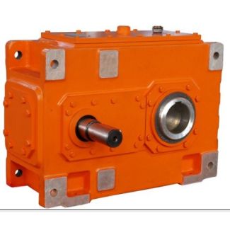

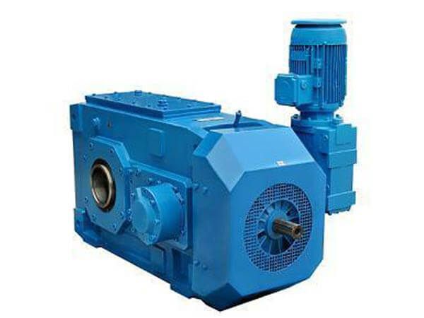
Helical speed reducers H1 flender d 46393 H1-SH15-B
In stock
SKU
H1-SH15-B
$68,571.43
Flender/Flender Gear Units/Helical speed reducers H1
__U B__U *)Only shaft mounted Mounting type: Foot-mounting design Shaft mounted designWall mounted design At housing side With IEC motor lantern Housing flange, short spacer Housing flange, long spacerWith swing base With HSS coupling Hydraulic type With base frame With
  LSS coupling Elastic type coupling Rigid typeWith torque reaction arm Motor type: With pedestal Shafts Designs for low speed shafts:Solid
  shaft with key Flange shaft Hollow shaft with key way Solid shaft for flange coupling **) with backlash free cone-clamping
  connection (without keyway)**)Cone-clamping flange coupling includedHollow shaft with shrink disk Hollow shaft with involute splines Special HS shaft dimensions: ( 1 l Shaft shoulder dimension: (G Special LS shaft dimensions: (d2 l Shaft shoulder dimension: (G2/G4/G Shaft arrangements: Double extended HS shaft Example: Double extended LS shaft Other options: (.. axial/radial force)General optionsSurface treatment ATEX Surface protection: C2 C3 C4 C5 Zone 1 2 2 2 Basic painting RAL 5 RAL Category Other options Gas Dust Group Additional cooling: Fan Cooling coil; cooling water input temperature IIA IIB IIC Cooler unit Oil/air Oil/water Temperature class Heater, with temperature control = , Hz, IPATEX-checklist customer Single rotation direction of the LS shaft: Right Left Backstopto mm Tol. mm mm Tol. mm LSS HSS Siemens AG 2 Appendix Conditions of sale and delivery 1/1 Siemens MD 3.1 2. General Provisions By using this catalog you can acquire hardware and software products described therein from Siemens AG subject to the following Terms and Conditions of Sale and Delivery (hereinafter referred to as "&"). Please note that the scope, the quality and the conditions for supplies and services, including software products, by any Siemens entity having registered office outside Germany, shall be subject exclusively to the General Terms and Conditions of the respective Siemens entity. The following & apply exclusively
| Model Type | Helical speed reducers H1 |
|---|---|
| Gear Type | Helical Gear |
| Weight (kg) | 3200.000000 |
| Ratio Range | 1 : 2…5.6 |
| Low Speed Output | Solid shaft with parallel key acc. to DIN 6885/1 |
| Nominal Torque | 130000 Nm |
| Mounting Arrangements | Horizontal mounting position |
| Manufacturer | Flender Singapore Pte. Ltd. |
| Country of Manufacture | Bulgaria |
| Data Sheet & Drawings | Helical speed reducers H1 flender d 46393 H1-SH15-B |
Related Products