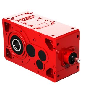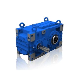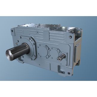
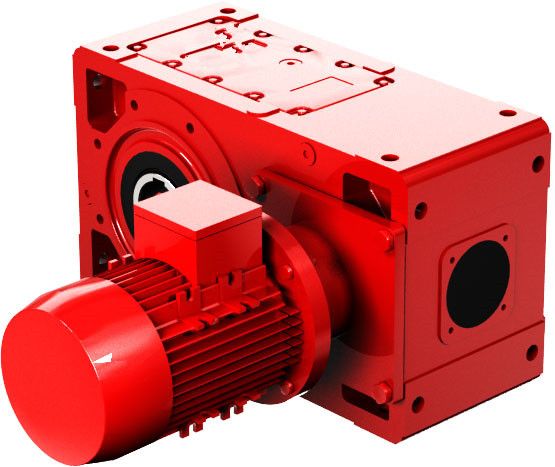

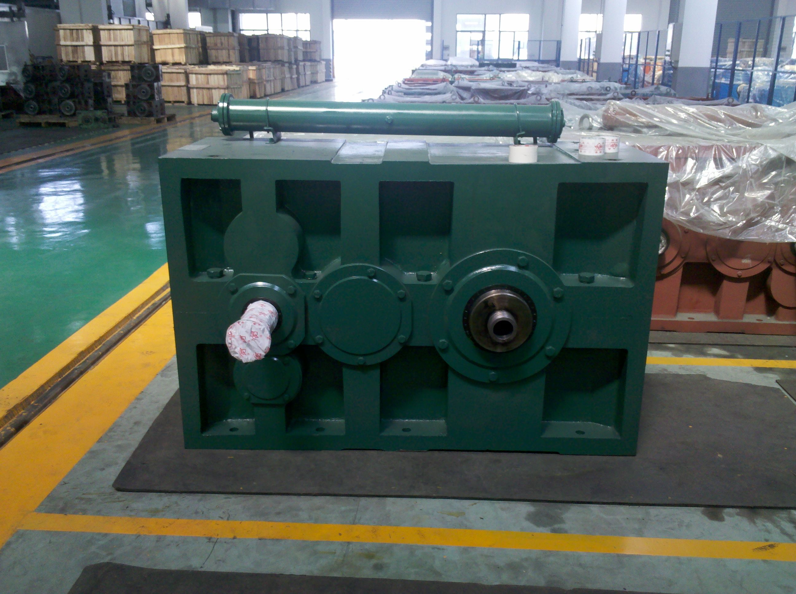
Bevel-helical gear unit B4 hafts see Chapter Cooling options see page B4SV-6-C
In stock
SKU
B4SV-6-C
$8,250.00
Flender/Flender Gear Units/Bevel-helical gear unit B4
stance . Configurable variants D1 ithout finished bore ith finished bore D2 ithout finished bore ith finished bore identify complete item numbers specifying the available finish boring options and if nec essary further order options, pl ease use our configurators
  on flender speed reducers. or online configuration on flender speed reducers, click on the item no. 6/3 TORSIONALLY RIGID ALL
  -STEEL COUPLINGS | ARPEX ARW-4/-6 SERIES 4 4 5 5 6 6 7 7 8 8 9 9 1 1
  1 1 1 1 1 1 A identify complete item numbers specifying the available finish boring options and if nec essary further order options, pl ease use our configurators on flender speed reducers. or online configuration on flender speed reducers, click on the item no.Ordering example RPEX ARW-4 NHN coupling, size 1-4, with shaft distance = 1 mm, ore D1 4H7 mm, with keyway to DIN 6 and set screw ore D2 4K7 mm, with keyway to DIN 6 and set screw Article no.: 2LC0-1AD9-0AZ0- L0W+M1A+Q0Y+M1 Plain text to Q0Y: = 1 mm Permitted shaft distance of type NHN relative to speed Size Speed nN DA 5 6 7 8 9 1 1 1 1 2 2 3 4 mm rpm Permitted shaft distance in mm 1-4 2 2 2 2 2 1 1 1 1 1 1 1 1 1-4 2 2 2 2 2 2 1 1 1 1 1 1 1 1-4 3 3 2 2 2 2 2 2 1 1 1 1 1 1-4 4 3 3 3 3 2 2 2 2 2 1 1 1 2-4 4 3 3 3 3 3 2 2 2 2 1 1 1 2-4 4 4 4 3 3 3 3 2 2 2 2 2 1 2-4 5 4 4 4 3 3 3 3 3 2 2 2 3-4 5 5 4 4 4 3 3 3 3 2 2 2 3-4 5 5 4 4 4 4 3 3 3 2 2 3-4 5 5 5 4 4 4 3 3 3 2 2 4-4 6 5 5 5 4 4 4 3 3 3 4-4 6 6 5 5 5 4 4 4 3 3 5-4 7 6 6 5 5 5 4 4 4 6-4 7 7 6 6 5 5 5 4 4 Outside the permitted speed range 6-4 7 7 6 6 5 5 5 4 4 6-6 8 7 6 6 6 5 5 4 4 7-6 8 7 7 6 6 6 5 8-6 8 7 7 6 6 6 5 8-6 8 8 7 6 6 6 Notes he permitted length of the intermediate spacer depends on the maximum operating speed of the coupling. In the case of ndividual order of the intermediate spacer, the length (LZ) must be specified. ass moments of inertia and weights apply to the entire NHN coupling with maximum bores D1/D2 and shaft distance = min.TYPE NHN 6/3
| Model Type | Bevel-helical gear unit B4 |
|---|---|
| Gear Type | Bevel Helical Gear |
| Weight (kg) | 385.000000 |
| Ratio Range | 1 : 100…400 |
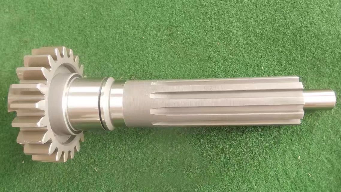
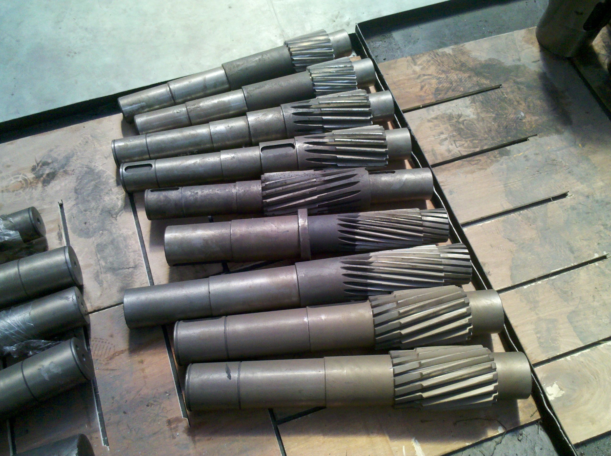
| Low Speed Output | Solid shaft with parallel key acc. to DIN 6885/1 |
| Nominal Torque | 15500 Nm |
| Mounting Arrangements | Vertical mounting position |
| Manufacturer | A. Fried. Flender AG |
| Country of Manufacture | China |
| Data Sheet & Drawings | Bevel-helical gear unit B4 hafts see Chapter Cooling options see page B4SV-6-C |
Related Products