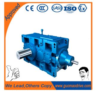

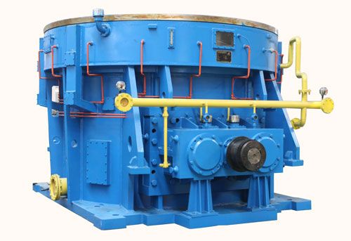
B4FV-12-C for ambient temperatures colder than C H Data po Bevel-helical gear unit B4
In stock
SKU
B4FV-12-C
$37,500.00
Flender/Flender Gear Units/Bevel-helical gear unit B4
y from Zyklo-Palloid blades on the HPG- method (see Sect. 2.. Instead of the prole blade (see Fig. 6., cutter bar carrier is placed in clamping device mounted on the surface of the cutter head.This clamping device is tilted relative
  to the surface of the cutter head by therequired tip clearance angle. The radial setting of the cutting edge is
  adjusted with2 6 Manufacturing Process distance plates. Each time the CBN cutting edge is re-ground at the cutting face, the
  cutter bar carrier is shifted in the clamping holder such that it is at the correct height. 6.5 Grinding Spiral Bevel Gears 6.5.1 Development History The rst bevel gear grinding machine was developed in the USA in the 1s, followed shortly by pinion machine with tilting axis for the tool [ HOFM3 ]. The grinding machines developed later were almost exclusively used for generatedspiral bevel gears in the aircraft industry and, despite their age, machines are stillfound in some manufacturing companies. Because of the lightweight constructionof the gear housing and the large resulting deections, the highest requirements are imposed on the ank topography and the tooth pitch of aircraft gears. Grinding is therefore almost essential as hard nishing process for these gear types. Attempts to use more modern grinding machines in the automotive industry during the 1s and 1s failed because their long machining and set-up timeswere not economically viable. The use of these machines, on which the tool couldno longer be tilted, was restricted to the 5-cut method. The breakthrough into large series production came only with the advent of CNC machines and exible numerical computation processes. In 1, the pioneer of CNC bevel gear grinding, Wiener, developed grinding machine for Formate wheels which had grinding spindle possessing second, eccentrically arranged, driven bearing sleeve (see Sect. 6.5.5.2 ). This allows avoiding full faced contact between the grinding wheel and the tooth ank. machine for pinion g
| Model Type | Bevel-helical gear unit B4 |
|---|---|
| Gear Type | Bevel Helical Gear |
| Weight (kg) | 1750.000000 |
| Ratio Range | 1 : 100…400 |
| Low Speed Output | Flanged shaft |
| Nominal Torque | 78000 Nm |
| Mounting Arrangements | Vertical mounting position |
| Manufacturer | Flender Ges.m.b.H. |
| Country of Manufacture | China |
| Data Sheet & Drawings | B4FV-12-C for ambient temperatures colder than C H Data po Bevel-helical gear unit B4 |
Related Products