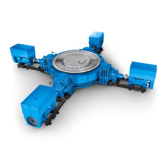
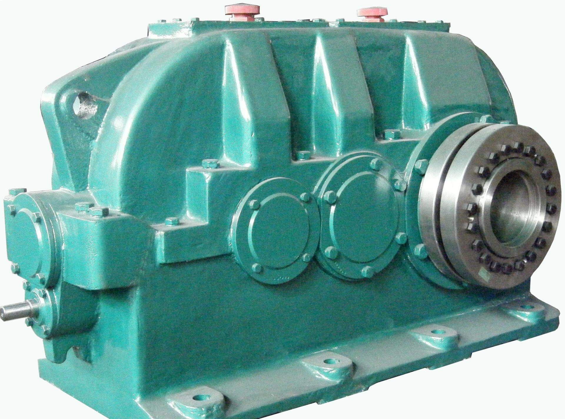
Bevel-helical speed reducer B4 p can be implemented for versions G H and I Dime B4FH-23-C
In stock
SKU
B4FH-23-C
$257,142.86
Flender/Flender Gear Units/Bevel-helical speed reducer B4
wo Standard Seals Mounting Positions For Factory Prelubrication Specify Mounting Position Blank No Lubrication M1-M9 Lubrication per Mounting Positions in CatalogOutput Shaft Blank Standard Carbon Steel Stainless MaterialNominal Gear Ratio (Rounded Value) Refer to Selection Tables For Available Ratios Lubrication
  Blank No Lubrication Klubersynth UH1 6-4 Klubersynth GH6 Mobil SHC 6 Mobil 6W (Sizes 3 and 4 are non-vented)Input Shaft
  Style Blank Solid Projecting Input Shaft Quill Style -Face Motor FlangeSeries 8B SeriesClutch/Brake Motor Common -Face Brakes Installed 1/2 VAC
  6hz Ft-LbBore Code CMBA5R-3 3 B5 CMBA5R-6 6 B5 CMBA1TR-6 6 B7 2-2/4 VAC 6hzFt-LbBore Code CMBA5U-3 3 B5 CMBA5U-6 6 B5 CMBA1TU-6 6 B7 Other sizes available. See catalog.Motor Conduit Box Orientation (When looking at fan end of motor) 0 1 Oclock 3 3 Oclock 6 6 Oclock 9 9 Oclock Reducer Material/Paint Blank Cast Iron, Std Gray Paint BK Cast Iron, White BostKleen Paint SBK Cast Iron, Stainless BostKleen PaintNEMA Motor Mounting BORE NEMA INPUT CODE MOUNTING BORE KEYWAY B5 5C .6 3/1 3/3 B7 1TC/1C .8 3/1 3/3 B9 1TC/2C 1.1 1/4 1/8 B1 2TC/2UC 1.3 5/1 5/3 Blank Solid Input Shaft (No Flange)*BK 8 3 2 4 B5 M1 CMBA5U-6 HUTF5/8-IDB 3 *Example: Above listed configuration is an example part number using this numbering system. How to Order Example: Required flange input NEMA 5C, and flanged output, 1/3 HP , Class , 4:1 ratio, lubricated, and standard mounting position. Order: 1 pc F8BF-4K-B5Common -Face Motors Installed HP RatingBore CodeAC Voltage 1/2-2-1-6 2-2/4-3-6 1/4 HP B5 DRTFB DUTFB 1/3 HP B5 ERTFB EUTFB 1/2 HPB5 FRTFBFUTFB B5 FUT-SS B5 FUTF-IDB 3/4 HPB5 GRTFBGUTFB B5 GUT-SS B5 GUTF-IDB 1 HPB5 HRTF-5/8BHUTF5/8B B5 HUT5/8-SS B5 HUTF5/8-IDB B7 HUTFB B7 HUT-SS B7 HUTF-IDB 1.5 HPB7 JUTFB B7 JUTF-SS B7 JUTF-IDB 2 HPB5 KUTF5/8B B7 KUTFB B7 KUTF-SS B7 KUTF-IDB 3 HPB9 LUTFB B9 LUTF-SS B9 LUTF-IDB 5 HP B9 MUT
| Model Type | Bevel-helical speed reducer B4 |
|---|---|
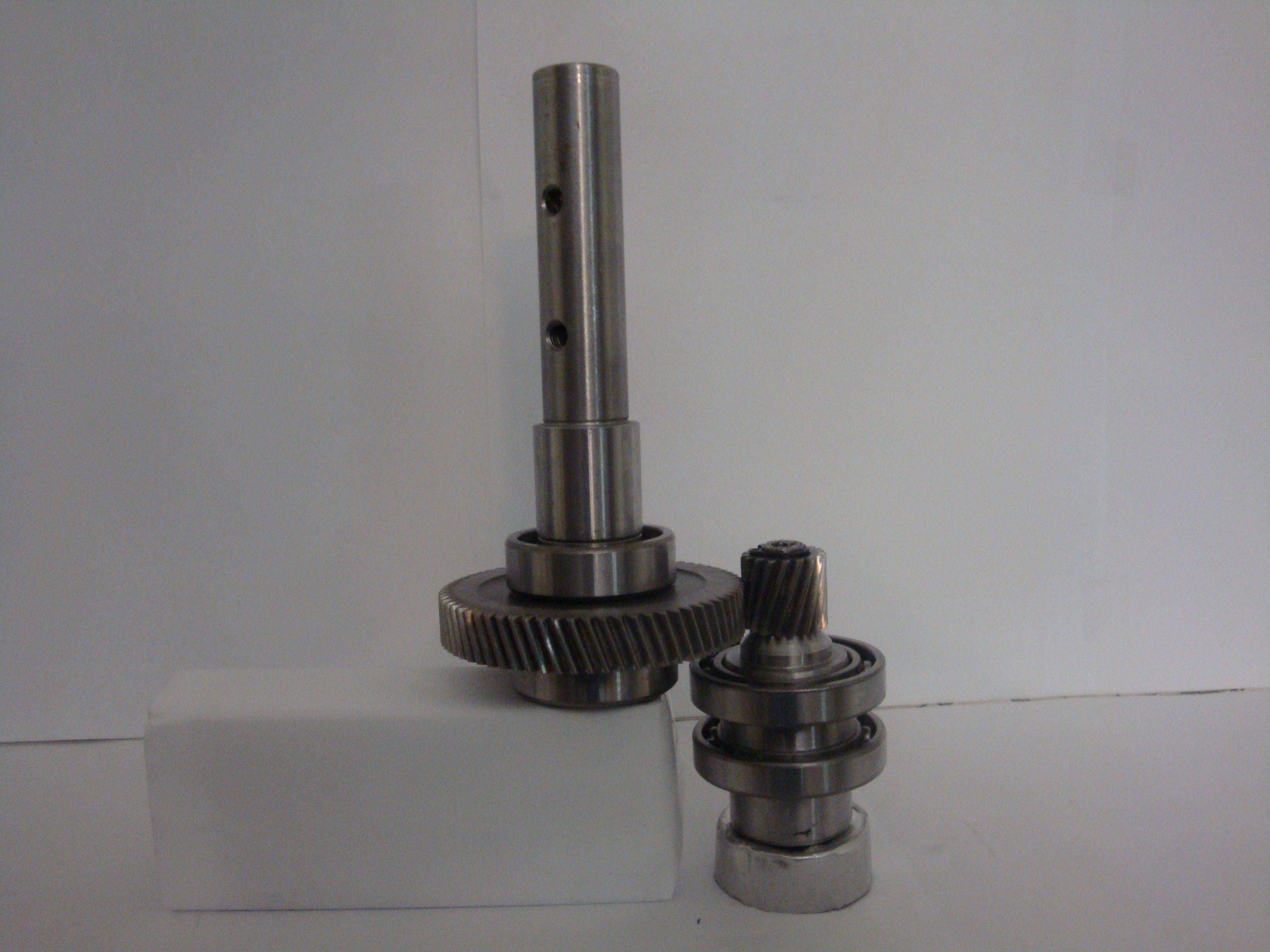
| Gear Type | Bevel Helical Gear |
| Weight (kg) | 12000.000000 |
| Ratio Range | 1 : 80…315 |
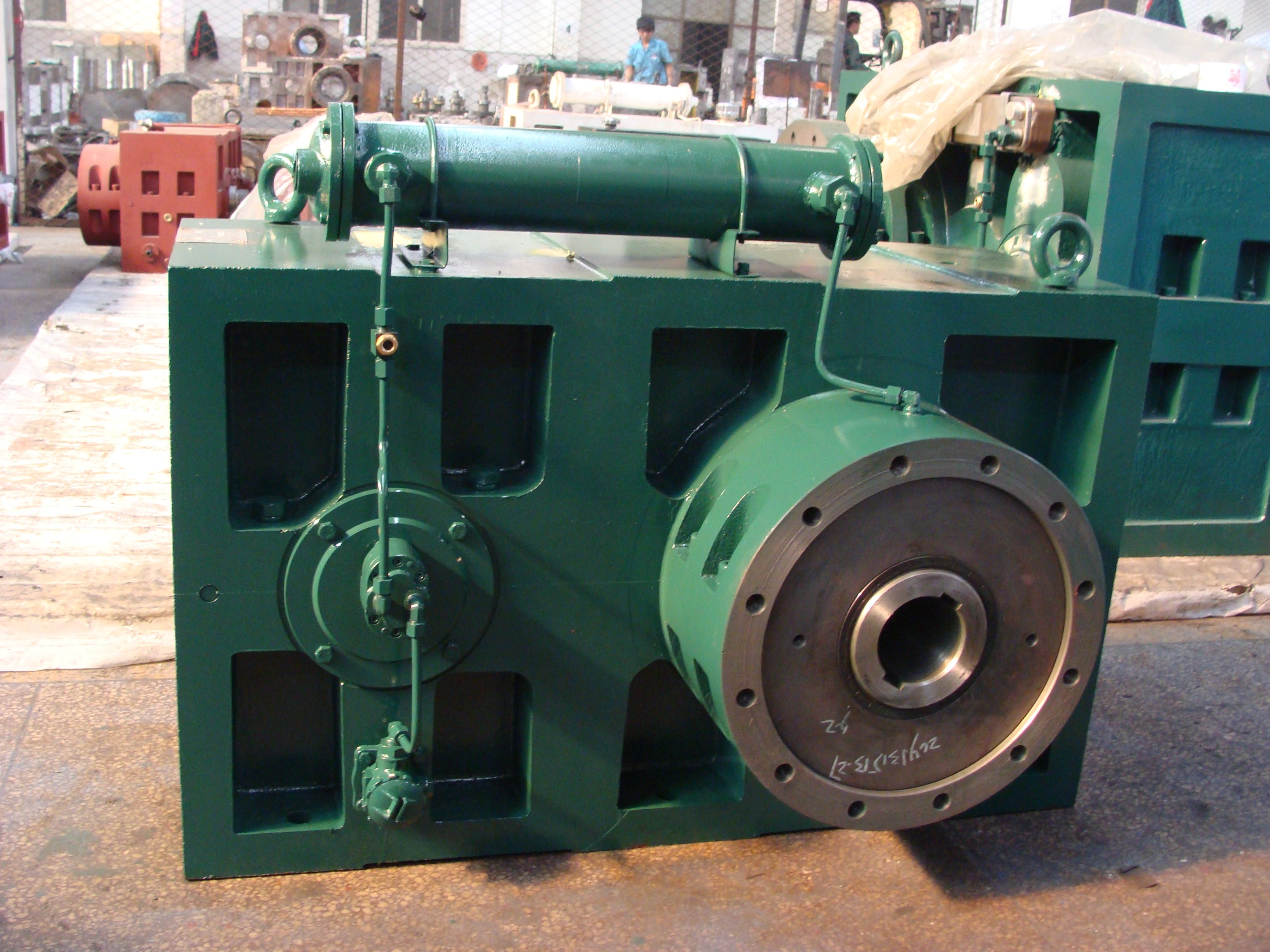
| Low Speed Output | Flanged shaft |
| Nominal Torque | 640000 Nm |
| Mounting Arrangements | Horizontal mounting position |
| Manufacturer | Flender Siemens |
| Country of Manufacture | Slovakia |
| Data Sheet & Drawings | Bevel-helical speed reducer B4 p can be implemented for versions G H and I Dime B4FH-23-C |
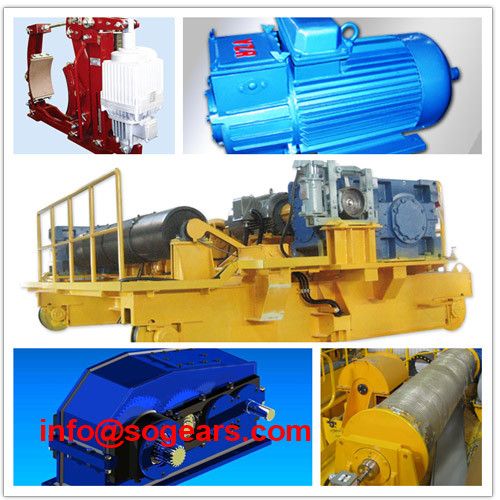
Related Products