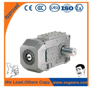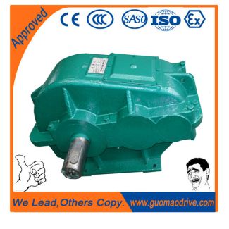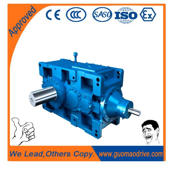

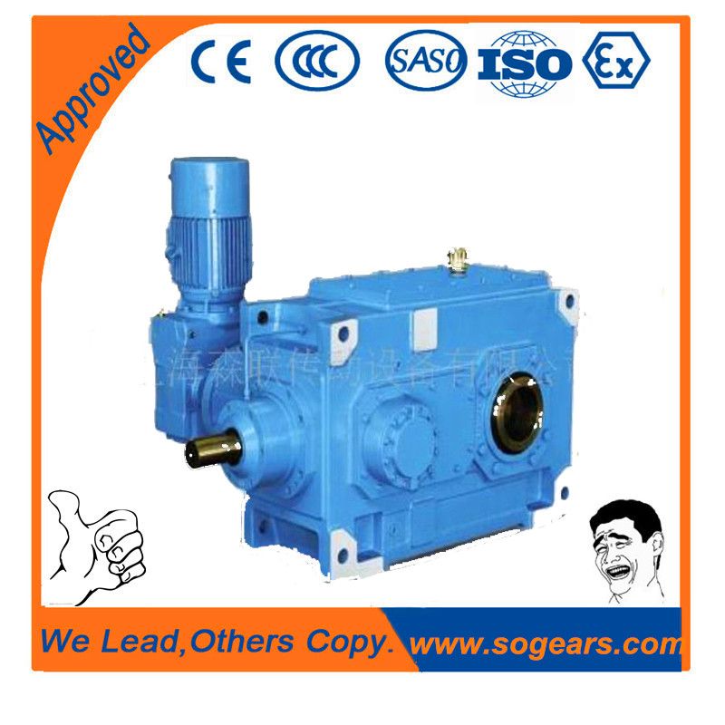
rds Shaft variant designed to withstand axia l for B4-SH-7B Bevel-helical speed reduction gearbox B4
In stock
SKU
B4-SH-7B
$11,892.86
Flender/Flender Gear Units/Bevel-helical speed reduction gearbox B4
sludge in each Module Reactor is maintained completely separate. WAS is wa sted directly from each reactor and gravitates to the dissolved air flotation (DAF) units for further thickening. The sizes of the ASP units are summarised in Table 4-1.
  4-4 Table 4-1: Sizes of ASP Units Treatment Unit Units Module 1 Module 2 Bioreactor Total volume m3 3,1 3,5
  Water depth Cell Volume (each per Reactor) Cell 1-Cell 9 m3 1,1 8 Cell 1 m3 1,0 1,0 Cell 1-Cell
  1 m3 2,0 1,7 Cell 1-Cell 1 m3 2,0 1,8 Internal mixed liquor recycle Maximum -recycle wrt ADWF No. 1:6 1:6 Maximum -recycle wrt ADWF No. 1:1 1:1 Secondary Settling Tanks No. of secondary clarifiers No. 4 4 Diameter 3 3 Side wall depth 3.5 3.5 Maximum RAS rate wrt. ADWF 1:1.5 1:1.5 4.2.5 Activated Sludge Aeration System Module 1 The aerobic compartments are aerated by fine-bubble diffused aeration system. During the construction of Module 2, the Module 1 aerobic cells were reconfigured to the same layout as Module 2 and the old diffusers were replaced with new EPDM membrane disc diffusers. Air is supplied by three Howden single stage centrifugal blowers (3 kW, each), two duty and one standby. summary of the blower and aeration control is given below. More details are given in the plant & manuals. Figure 4-3: Module 1 Single Speed Centrifugal Blowers (Photo Courtesy City of Tshwane) 4-5 The blowers deliver air to common manifold equipped with an airflow meter and pressure transmitter. The air flow splits to each reactor where it feeds th swing cells (9 & and aerobic cells (1-. There are four DO sensors located in each aerobic cell (1-. The chief Operator modified the original blower control and traditional fixed DO control algorithm and developed new aeration control algorithm that take into account manually observed final effluent ammonia concentrations. The modified cont rol strategy is summarised as follows: () Operator sets bl
| Model Type | Bevel-helical speed reduction gearbox B4 |
|---|---|
| Gear Type | Bevel Helical Gear |
| Weight (kg) | 555.000000 |
| Ratio Range | 1 : 80…315 |
| Low Speed Output | Solid shaft with parallel key acc. to DIN 6885/1 |
| Nominal Torque | 21700 Nm |
| Mounting Arrangements | Horizontal mounting position |
| Manufacturer | PT Flenindo Aditransimisi |
| Country of Manufacture | Israel |
| Data Sheet & Drawings | rds Shaft variant designed to withstand axia l for B4-SH-7B Bevel-helical speed reduction gearbox B4 |
Related Products