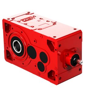
B4-KV-5B for cooling for which no additional cooling medi Bevel-helical gear reducer B4
In stock
SKU
B4-KV-5B
$7,178.57
Flender/Flender Gear Units/Bevel-helical gear reducer B4
uxiliary cooling by fan and cooling coil, connections to gear unit face 1 (end face d 5 Additional details see page 1/2. Siemens AG 2 Siemens MD 3.1 2 5/2 Type H1 Gear unit dimensions 5/2 Single-stage, gear unit sizes
  5 to 5 5/4 Single-stage, gear unit sizes 5 and 5 5/6 Type H2Gear unit dimensions 5/6 Two-stage, gear unit
  sizes 5 and 5 5/8 Type H3Gear unit dimensions 5/8 Three-stage, gear unit sizes 5 and 5 5/1 Type H4Gear
  unit dimensions 5/1 Four-stage, gear unit sizes 5 and 5 5/1 Four-stage, gear unit sizes 5 to 5 5/1 Types H1, H2, H3 and H4 5/1 Dimensions of oil expansion unit 5/1 Article No. overview Helical gear units vertical mounting position Siemens AG 2 Helical gear units vertical mounting position Type H1 Gear unit dimensions Single-stage, gear unit sizes 5 to 5 5/2 Siemens MD 3.1 2Selection and ordering data G_MD3_EN_0bg c1Eh 6 an6 n3b3 b4l1 G1H b2 b2 n4 n4 f d1 5 Dimensions in mm Gear unit sizesInput d1 l1 d1 l1 d1 l1 G1 iN =1.1 2.8 3.1 4 4.5 5.6 5 6 m6 1 4 m6 1 3 m6 8 2 iN =1.1 2.8 3.1 5.6 5 7 m6 1 5 m6 1 2 iN =1.1 2.8 3.1 4 4.5 5.6 5 8 m6 1 6 m6 1 5 m6 1 2 iN =1.4 3.5 4 5 5.6 5 8 m6 1 6 m6 1 5 m6 1 2 iN =1.1 2.8 3.1 4 4.5 5.6 5 1 m6 1 8 m6 1 7 m6 1 2 iN =1.3 3.3 3.7 4.7 5.3 6 5 1 m6 1 8 m6 1 7 m6 1 2 Gear unit sizes Dimensions in mm b2 b3 b4 c1 D5 f2 h6 n3 n4 n6 5 4 2 9 2 7 2 1 1 5 1 4 2 1 2 1 1 5 5 3 1 2 9 3 2 1 5 1.5 4 2 2 2 1 1 5 6 3 1 2 1 3 2 1 6 1 5 2 2 3 2 2 5 6 3 1 3 1 3 2 2 6 1 5 2 2 3 2 2 5 7 4 1 3 1 4 2 2 6 1.5 6 3 2 4 2 2 5 7 4 1 3 1 4 2 2 6 1.5 6 3 2 4 2 2 Note: "Dip lubrication with oil expansion unit" is provided as the standard oil supply. Dimensions of oil expansion unit see page 5/1. For shaft details, see pages 1/2 to 1/7. Position dependent on other options. Minimum dimensions, space requirem ents dependent on other options. Permissible tolerance: -1 mm. Siemens AG 2 Helical gear units vertical mounting position Type H1 Gear unit dimensions S
| Model Type | Bevel-helical gear reducer B4 |
|---|---|
| Gear Type | Bevel Helical Gear |
| Weight (kg) | 335.000000 |
| Ratio Range | 1 : 80…315 |
| Low Speed Output | Hollow shaft with spline acc. to DIN 5480 |
| Nominal Torque | 11600 Nm |
| Mounting Arrangements | Vertical mounting position |
| Manufacturer | Flender Corporation |
| Country of Manufacture | Saudi Arabia |
| Data Sheet & Drawings | B4-KV-5B for cooling for which no additional cooling medi Bevel-helical gear reducer B4 |
Related Products