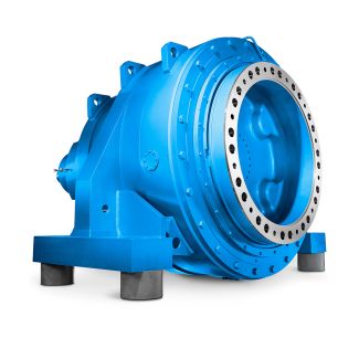
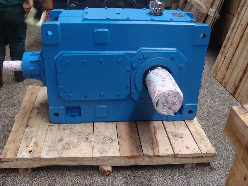
ic flow is adapted at any time to the current need B4-KH-13-D Bevel-helical speed reducers B4
In stock
SKU
B4-KH-13-D
$51,321.43
Flender/Flender Gear Units/Bevel-helical speed reducers B4
urn down constant torque) B5 5C B7 1TC B9 1TC FLENDER GRAFFENSTADEN bostongear speed reducers -1-BG 5/1HFOR RATINGS AT OTHER INPUT SPEEDS, SEE TABLES ON PAGES 2-2. ORDER BY CATALOG NUMBER OR ITEM CODE FOR STANDARD MOUNTING POSITIONS Approx. Output
  RPMNominal Ratio*NON-FLANGED FLANGED (GEARMOTORS) GEAR CapacityCatalog Number (Item Code)Motor HPRatings Output TorqueService Class**Catalog Number (Item Code) Shaft MountedOutput TorqueHP Input
  3 5 2 .2S8BR-5K (F0)2 1 .5 2I IISF8BR-5K-B7 (F0) 1 1 IIISF8BR-5K-B5 (F0) 5 3 .7S8BR-5K (F0)3 4 ISF8BR-5K-B9
  (F0) 1 .5 2II III SF8BR-5K-B7 (F0) * Gear Ratio is Approximate. For Actual Gear Ratio Reference Pages 2-2. ** Service Class (. . = 1.0) Service Class ll (. . = 1. Service Class lll (. . = 2.0) Overhung Load Ratings refer to Page 2.8 Series Right Angle Helical-Worm Selection Tables FLENDER GRAFFENSTADEN 1 RPM Input8 Series Right Angle Helical Worm Gear Drives Motorized Gear Drives 1 . Deter mine application service factor from page 2 or from Application Classifications on page 3-3. 2. Determine output speed required. 3. Determine HP or output torque requirement. 4. Select based on output speed and horsepower requirement for given service class. 5. Check overhung load Ref. calculation. Example Select right angle motorized helical-worm shaft mounted gear drive and motor to drive uniformly loaded line conveyor 2 hours/day requiring 2 HP at 3 RPM. Power Requirement 2/4 volt 3 phase 6 hertz 1. Select Service Factor Class from page 2. Service Class = II 2. Output RPM = 3 3. 2 HP 4. Select 2 HP drive that will satisfy min. of II service class. 5. Order: 1 - SF8BR-5K-B7 (F0) Ref. Page 2 1 - KUTF Motor Overhung Load (Not Required for Example) If the output shaft of gear drive is connected to the driven machine by other than flexible coupling, an overhung load is imposed on the shaft. This load may be calculated as follows: OHL = 2 TK OHL = Overhung Load (LB.) = Shaft Torque (LB.-INS.)
| Model Type | Bevel-helical speed reducers B4 |
|---|---|
| Gear Type | Bevel Helical Gear |
| Weight (kg) | 2395.000000 |
| Ratio Range | 1 : 80…315 |
| Low Speed Output | Hollow shaft with spline acc. to DIN 5480 |
| Nominal Torque | 90700 Nm |
| Mounting Arrangements | Horizontal mounting position |
| Manufacturer | Siemens Flender |
| Country of Manufacture | Iran |
| Data Sheet & Drawings | ic flow is adapted at any time to the current need B4-KH-13-D Bevel-helical speed reducers B4 |
Related Products