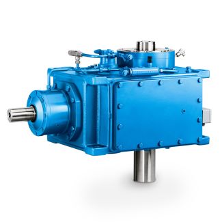

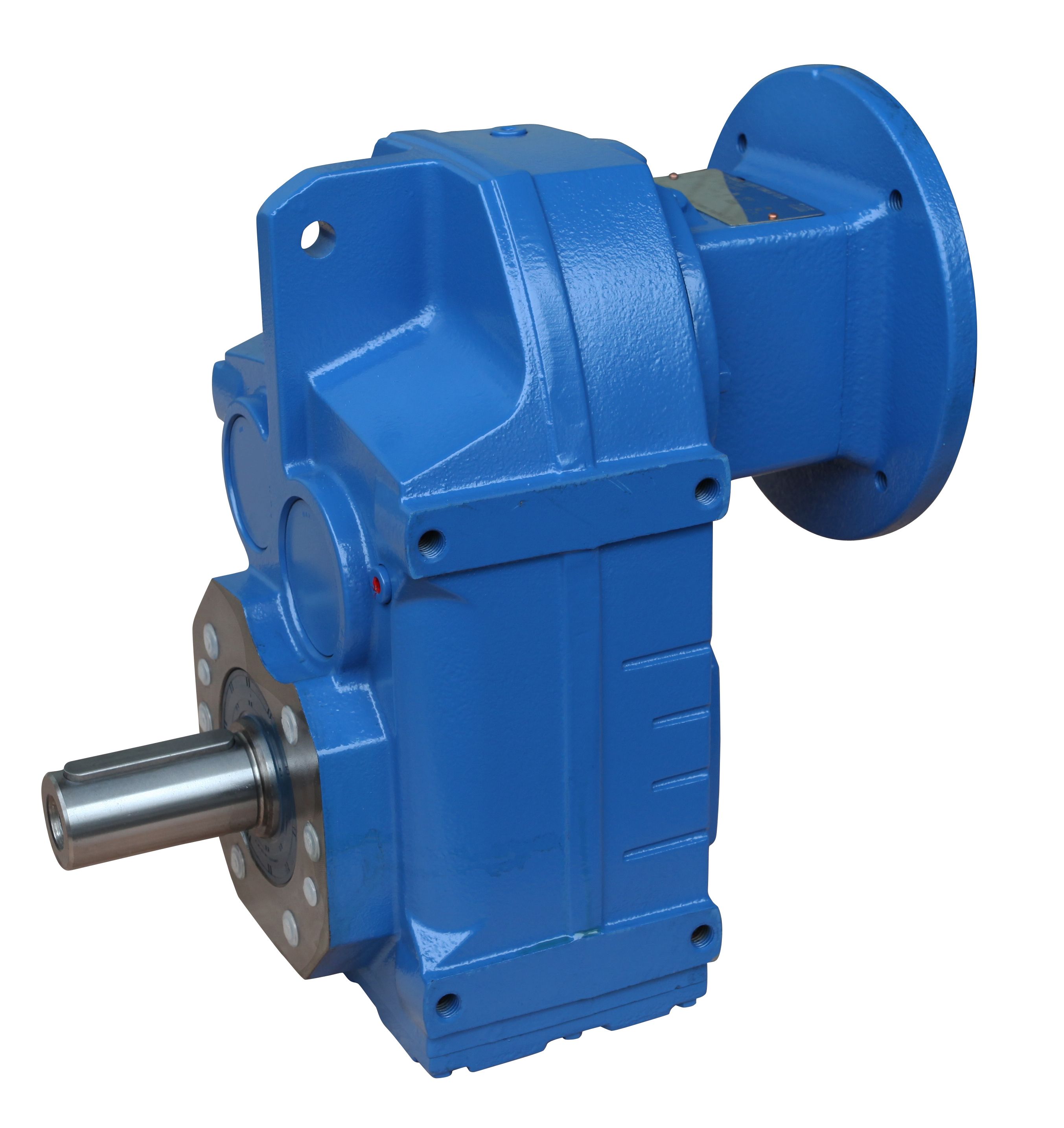
in Gear unit in mounting position H Oil drain val B4-FV-24-A Bevel-helical speed reducer B4
In stock
SKU
B4-FV-24-A
$289,285.71
Flender/Flender Gear Units/Bevel-helical speed reducer B4
ywheel which in turn was coupled with 5.5 kV Mecc Alte Spa three phase alternator to apply the load. The instantaneous gear and pinion angular positions and velocities were estimated from synchronising pulse which was measured by means of proximity
  switch on the key of the E2A gear shaft. The gear casing acceleration response was measured in the vertical direction
  by means of 1 / PCB integrated circuit piezoelectric industrial accelerometer. The measurements were taken with Siglab model 2-4 signal
  analyser at sampling frequency of 5.2 kHz. number of time-varying loading conditions were investigated. The load conditions are summarized in Table 5. Table 5: Load case specications Load case Load function Frequency Minimum load Maximum load 1 Sine 0.5 Hz 7.4Nm 1.7 Nm 2 Sine 1 Hz 7.4Nm 1.7 Nm 3 Square 0.5 Hz 7.4Nm 1.7 Nm 4 Square 1 Hz 7.4Nm 1.7 Nm 5 Chrip 0.1-2 Hz 7.4Nm 1.7 Nm 6 Random 0.1-2 Hz 7.4Nm 1.7 Nm Four measurements for each load condition were recorded. The rst measurement represented the healthy gearbox. Flank wear was subsequently induced on one of the gear teeth by progressively removing more of the gear tooth face. Each measurement was recorded for 3s. Table 6: Seeded gear damage condition Measurement Fault severity 0 Good condition 1 1mmtooth face removal 2 2mmtooth face removal 3 3mmtooth face removal The subsequent sections investigate the vibration signal, the vibration based synchronous average, the spectrum analysis, the NLL discrepancy transform and the NLL synchronous average. The magnitude of the results vary slightly depending on the load scenario, however the nature of the results remain fairly consistent. For this reason one load scenario, namely the 0.5 Hz sinusoidal load scenario will consistently be used to visualise the application of the techniques. Time domain waveform The time domain waveform for load scenario 2, with the 0.5 Hz sinusoidal component, is illustrated in gures 8 ()-(), where () represents the healthy waveform, and
| Model Type | Bevel-helical speed reducer B4 |
|---|---|
| Gear Type | Bevel Helical Gear |
| Weight (kg) | 13500.000000 |
| Ratio Range | 1 : 90…355 |
| Low Speed Output | Flanged shaft |
| Nominal Torque | 725000 Nm |
| Mounting Arrangements | Vertical mounting position |
| Manufacturer | Flender Ges.m.b.H. |
| Country of Manufacture | Indonesia |
| Data Sheet & Drawings | in Gear unit in mounting position H Oil drain val B4-FV-24-A Bevel-helical speed reducer B4 |
Related Products