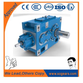
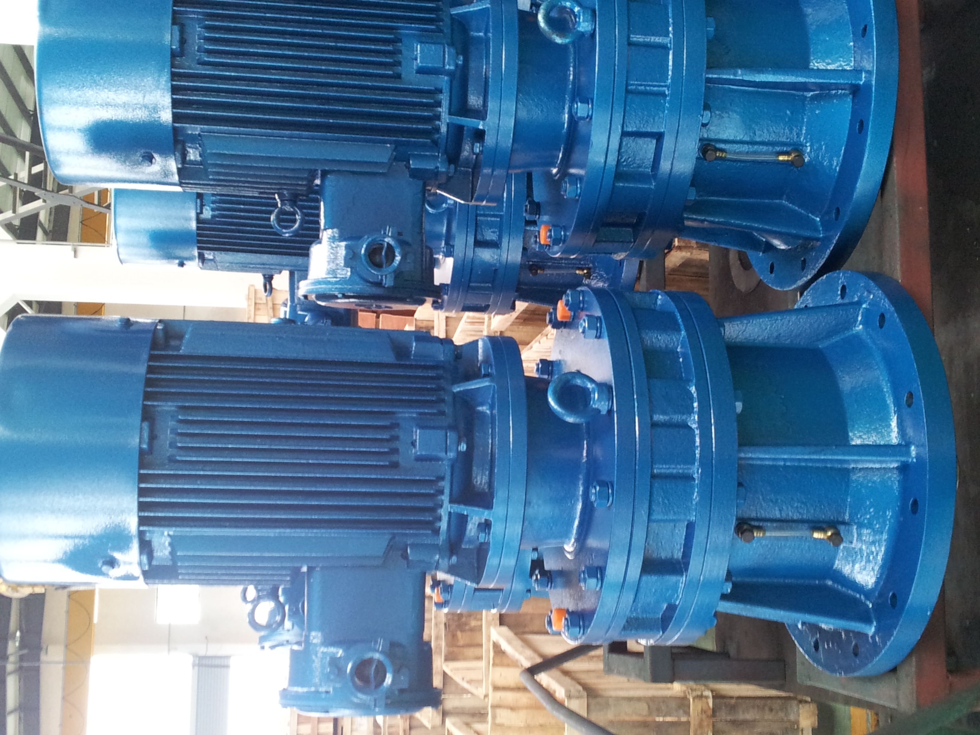
liary cooling Radial fan standard version with B4-DV-25-D Bevel-helical speed reduction gearbox B4
In stock
SKU
B4-DV-25-D
$349,285.71
Flender/Flender Gear Units/Bevel-helical speed reduction gearbox B4
unique #3L Stainless Steel Leafing Pigment. This catalyzed system creates HARD, NON-TOXIC METALLIC FINISHBost-Kleen WASH DOWN BISSC Certified Basic Model Numbers, Dimensions And Available Ratios White BOST-KLEEN Stainless BOST-KLEEN Center DistanceNEMA MountingInput Shaft Dia. +.0 -.0Output Shaft Dia. +.0 -.0Available
  RatiosNON- FLANGED TypeQuill TypeNON- FLANGED TypeQuill Type BK2 BKF2 SBK2 SBKF2 2 .1 5C .5 1 .0 4,1,1,1,2,2 BK2 BKF2
  SBK2 SBKF2 2 .6 5C,1TC .6 1 .2 4,1,1,1,2,2 BK2 BKF2 SBK2 SBKF2 3 .1 5C,1TC,1TC .9 1 .3 4,1,1,1,2,2
  BK2 BKF2 SBK2 SBKF2 3 .8 1TC,1TC, 2TC 1 .3 1 .8 4,1,1,1,2,2 BK2 BKF2 SBK2 SBKF2 4 .6 1TC,2TC 1 .5 2 .1 4,1,1,1,2,2 -1-BG 5/1 FLENDER GRAFFENSTADEN bostongear speed reducersJ2 Series Optimount Helical Gear Speed Reducers Installation, Lubrication and Operation Instructions General Instructions 1. When mounting, use maximum possible bolt size and secure gear drive to rigid foundation. Periodic inspection of all bolts is recommended. 2. Align all shafts accurately. Improper alignment can result in failure. Use of flexible couplings is recommended to compensate for slight misalignment. 3. Arrange the drain and breather plug per your mounting position as indicated on page 2. The breather plug should also be located in the Fill position. 4. Auxiliary drive components (such as sprockets, gears and pulleys) should be mounted on the shafts as close as possible to the housing to minimize effects of overhung loads. Avoid force fits that might damage bearings or gears. 5. Gear drives are nameplated for 1 RPM Input Speed and Class Service. For lower Input Speeds and other Service Class, refer to catalog rating information 6. Input Speeds of 1 and lower are shown in catalog rating tables for speed reducing applica tions. This does not represent the maximum speed. Since speed limitation is based on pitching velocity and varies with size and ratio.Shaft Mounted Installation Mount reducer on the shaft to be driven, as c
| Model Type | Bevel-helical speed reduction gearbox B4 |
|---|---|
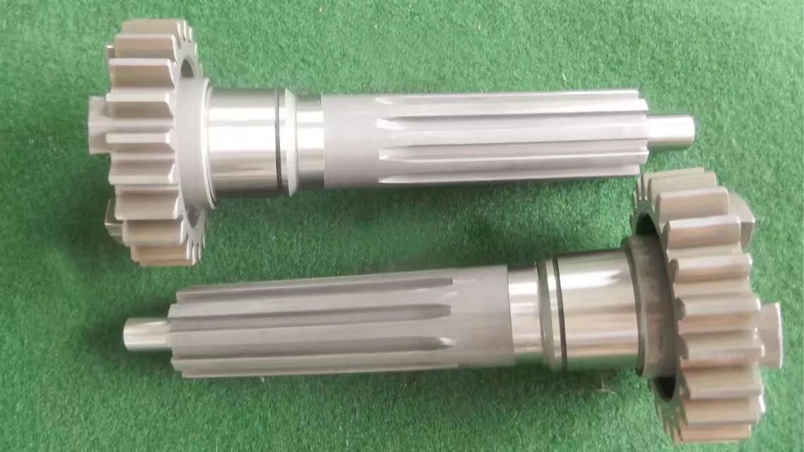
| Gear Type | Bevel Helical Gear |
| Weight (kg) | 16300.000000 |
| Ratio Range | 1 : 80…315 |
| Low Speed Output | Hollow shaft with shrink disk |
| Nominal Torque | 860000 Nm |
| Mounting Arrangements | Vertical mounting position |
| Manufacturer | Flender Bocholt |
| Country of Manufacture | Bolivia |
| Data Sheet & Drawings | liary cooling Radial fan standard version with B4-DV-25-D Bevel-helical speed reduction gearbox B4 |
Related Products