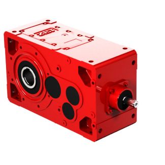
fan ATEX design with dualside high speed shaft H B4-DV-26-D Bevel-helical gear boxes B4
In stock
SKU
B4-DV-26-D
$385,714.29
Flender/Flender Gear Units/Bevel-helical gear boxes B4
unit sizes 5 to 5 1/1 Siemens MD 3.1 2Overview Depending on the version, screw-in heaters and temperature monitors/resistance thermometers can be arranged in mirror image. The cable entry point of the screw-in heater is arranged axially on the connection
  head in the direction of installation. h1 l4 l1 e4 e1e2h1h2 bbe3e3 G_MD3_XX_0Installation space requiredInstallation space required Connected load in
  Dimensions in mm Gear unit size Heating elements Heating elements Installation space Temperature monitors 1 heating element2 heating elements e1
  e4 h1 l1 l4 e2 e3 h2 5 3 6 3 5 4.5 4 5 5 3 5 1 5 4 6 3 6 4.5 4 7 7 4 5 1 5 4 9 3 6 5 6 8 8 3 6 1 5 5 8 4 7 5 6 9 9 4 6 1 5 8 1 4 8 6 7 7 7 4 8 2 5 1 1 5 8 6 7 9 9 5 8 2 5 1 2 5 9 7 8 1 1 5 8 2 5 1 2 5 1 7 8 1 1 5 8 2 5 1 2 4 1 8 8 1 1 5 1 3 5 1 2 4 1 8 8 1 1 5 1 3 Screw-in heater: Technical data and notes: IP 6 degree of protection, 2 , 5 Hz. Temperature monitor ATH-SW2: Technical data and notes: IP 6 degree of protection, two change-over contacts (adjustable). Max. contact rating: 2 /2 AC/4 VA cos = 0.6 (alternating voltage); 0.2 /2 DC/5 (direct voltage) Or alternatively: Pt1 resistance thermometer: Technical data and notes: Connection head IP 5 degree of protection, PG 9, two-wire circuit Connection with three or four-wire circuit also possible by the customer. Connection to an evaluation unit is necessary. With sizes 5, 5, 5, 5 and 5 it is not possible to mount 2 heating elements on gear unit face 4 (end-face output)! Siemens AG 2 Options for operation Heating Heating elements Types H4 and B4, gear unit sizes 5 to 5 1/1 Siemens MD 3.1 2Overview Depending on the version, screw-in heaters and temperature monitors/resistance thermometers can be arranged in mirror image. The cable entry point of the screw-in heater is arranged axially on the connection head in the direction of installation. h1 l4 l1 e4 e1e2h1h2 bbe3e3 G_MD3_XX_0Installation s
| Model Type | Bevel-helical gear boxes B4 |
|---|---|
| Gear Type | Bevel Helical Gear |
| Weight (kg) | 18000.000000 |
| Ratio Range | 1 : 90…355 |
| Low Speed Output | Hollow shaft with shrink disk |
| Nominal Torque | 1030000 Nm |
| Mounting Arrangements | Vertical mounting position |
| Manufacturer | Siemens AG |
| Country of Manufacture | Brunei |
| Data Sheet & Drawings | fan ATEX design with dualside high speed shaft H B4-DV-26-D Bevel-helical gear boxes B4 |
Related Products