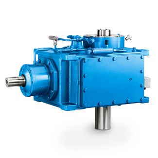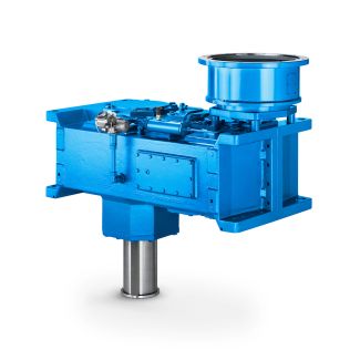
er from a dirty filter element to a clean one dur B4-DV-13-D Bevel-helical gear Reduction Boxes B4
In stock
SKU
B4-DV-13-D
$51,321.43
Flender/Flender Gear Units/Bevel-helical gear Reduction Boxes B4
ugh 1 kVA, 1.4 / 0.4 kV transformer. Since the wind turbine is rated to 6 an additional 8 kVA, 0.4 / 0.6 kV transformer is installed to step up the voltage from 4 to the wind turbine level. The
  electric connection diagram is shown in Figure 1. Gear box5 kW induction generatorMain circuit breaker Capacitor bank0.6/0.4 transfoSoft starterBy-pass contactor
  0.4/1.4 transfo 1 kV1 kW Tellus windturbine Measurement pointGrid 4 V6 Figure 1: Connection diagram for NTK 5/4 wind turbine.
  WIND TURBINE INSTRUMENTATION The idea of establishing WTMLAB is to enable the students to explore experimentally the mechanical conversion of wind power to electric power on an operating wind turbine, with focus on four main areas: Meteorological measurements to describe the inflow, Structural measurements to analyze the dynamic response, Control and power measurements to study the operational behavior. Electrical measurements to examine the interaction between wind turbine and the electrical grid. Presented at EWEC 2, Athens 2 February 2 March 2 Page 3/8 meteorological mast is placed 2.5 rotor diameters in westerly direction from the wind turbine. The mast is equipped with standard instrumentation as listed in Table 2. The installation is made in accordance with the recent IEC recommendations for both power performance and structural load measurements. Wind speed, =3m / Wind direction, =3 Deg Temperature, =3 DegC Atmospheric pressure,=3 mmBar Meteorological measurements Rain, =3 mm/hour Table 2: Meteorological sensors. The structural loads are monitored by strain gauges mounted at the blade root, on the main shaft, at the tower top and at the tower bottom as listed in Table 3. The instrumented locations are described below: Blade loads: The load signals from the reference blade includes bending moments at the blade root, measured as strain gauge signals located on the blade root steel extenders, as shown on Figure 2. The g
| Model Type | Bevel-helical gear Reduction Boxes B4 |
|---|---|
| Gear Type | Bevel Helical Gear |
| Weight (kg) | 2395.000000 |
| Ratio Range | 1 : 80…315 |
| Low Speed Output | Hollow shaft with shrink disk |
| Nominal Torque | 90700 Nm |
| Mounting Arrangements | Vertical mounting position |
| Manufacturer | Flender Industriegetriebe GmbH |
| Country of Manufacture | South Korea |
| Data Sheet & Drawings | er from a dirty filter element to a clean one dur B4-DV-13-D Bevel-helical gear Reduction Boxes B4 |
Related Products