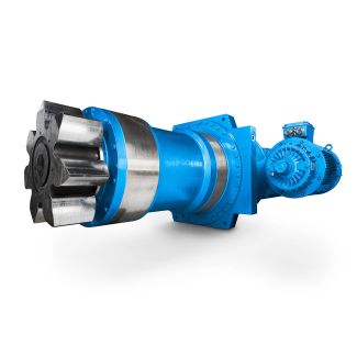
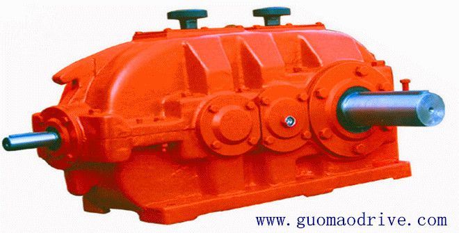
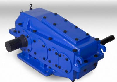
Bevel-helical speed reducer B4 input speed n is undershot radial shaft seals mus B4-DH11A
In stock
SKU
B4-DH11A
$31,821.43
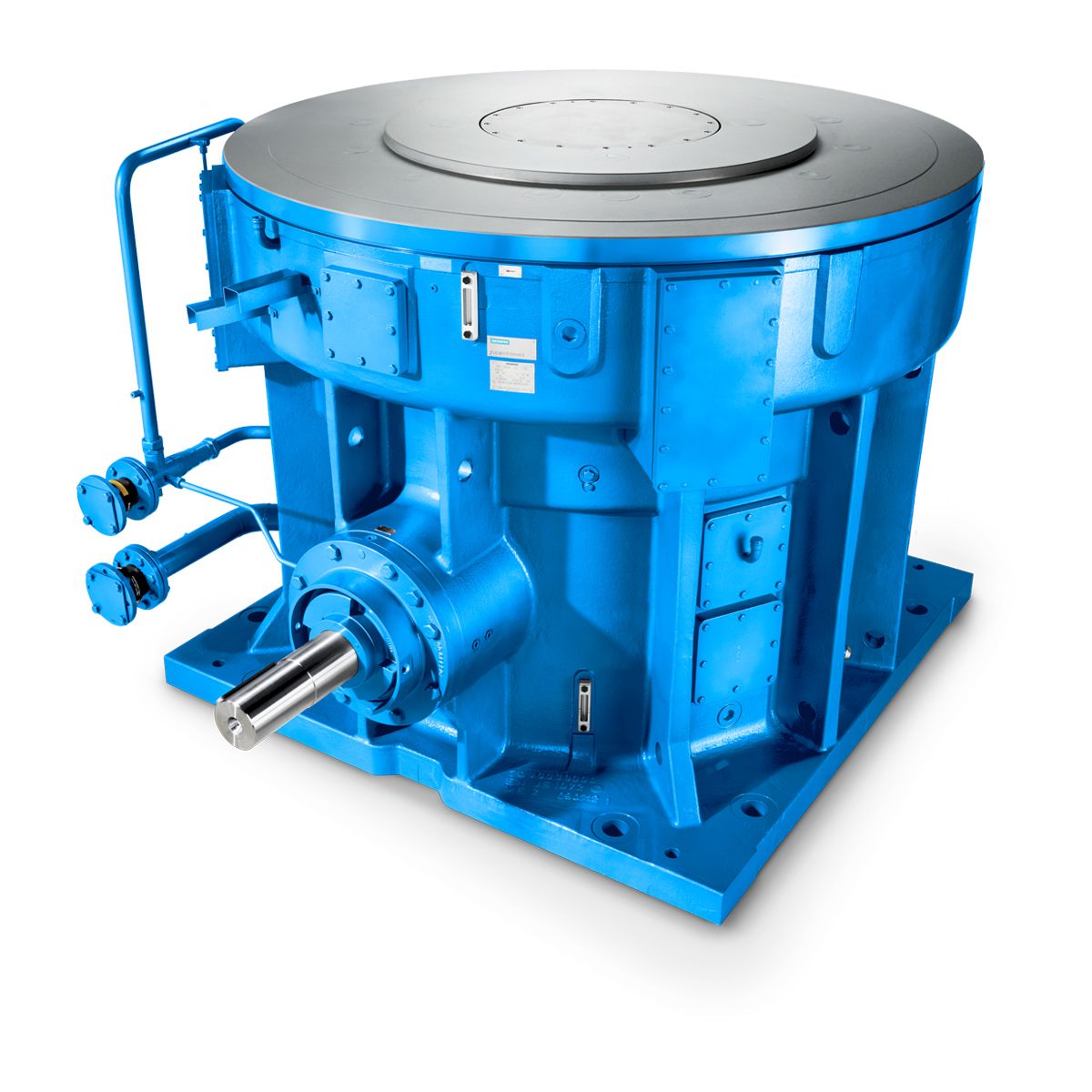
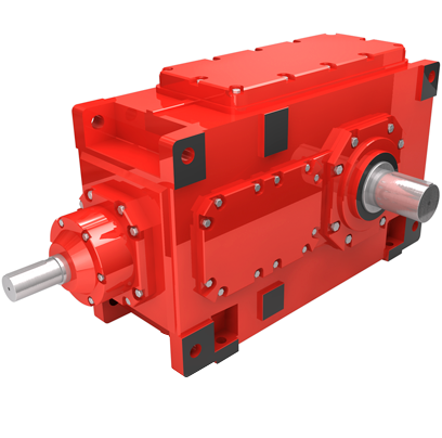
Flender/Flender Gear Units/Bevel-helical speed reducer B4
tter, including sealant and made up to full thread engagement before seal welding. 4.8 Flange Connections All flange facings shall be true and perpendicular to the axis attached. Flanged bolt holes shall straddle the normal centerli nes unless different orientation
  is shown in the drawing. Wherever spectacle blind is to be provided, drilling and tapp ing for the jack screws
  in the flange, shall be done before welding it to the pipe. 4.9 Branch Connections Branch connections shall be as
  indicated in the piping material . preparation, alignment, spacing, fit-up and welding of branch connections refer welding specifications. Templates shall be used wherever required to en sure accurate cutting and proper fit-up. For all branch connections accomplished either by pipe to pipe connections or by using forged tees the rates quoted for piping shall be inclusive of this work. Reinforcement pads shall be provided wherever indicated in draw ings/ specifications etc. 4.1 Bending Bending shall be as per ASME B3.3 except that corrugated or creased bends shall not be used. Cold bends for lines 1-1/2" and below, with bend radius of 5 times the nominal diameter shall be used as required in place of elbows wherever allowed piping specifications. Bending of pipes 2" and above may be required in some cases lik that for headers around heaters, reactors etc. The completed bend shall have smooth surface, free from crack , buckles, wrinkles, bulges, flat spots and other serious defects. They shall be true to dimensions. The flattening of bend, as measured by the difference between the maximum and min imum diameters at any cross-section, shall not exceed 8% and 3% of the nominal outsid diameter, for internal and external pressure respectively. 4.1 Forging and forming Forging and forming of small bore fittings, like reducing nippl es for piping 1-1/2" and below, shall be as per ASME 3.3. 1 of 1 STANDARD T
| Model Type | Bevel-helical speed reducer B4 |
|---|---|
| Gear Type | Bevel Helical Gear |
| Weight (kg) | 1485.000000 |
| Ratio Range | 1 : 80…315 |
| Low Speed Output | Hollow shaft with shrink disk |
| Nominal Torque | 61600 Nm |
| Mounting Arrangements | Horizontal mounting position |
| Manufacturer | A. Fried. Flender AG |
| Country of Manufacture | Chile |
| Data Sheet & Drawings | Bevel-helical speed reducer B4 input speed n is undershot radial shaft seals mus B4-DH11A |
Related Products