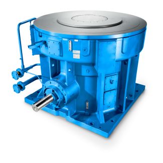
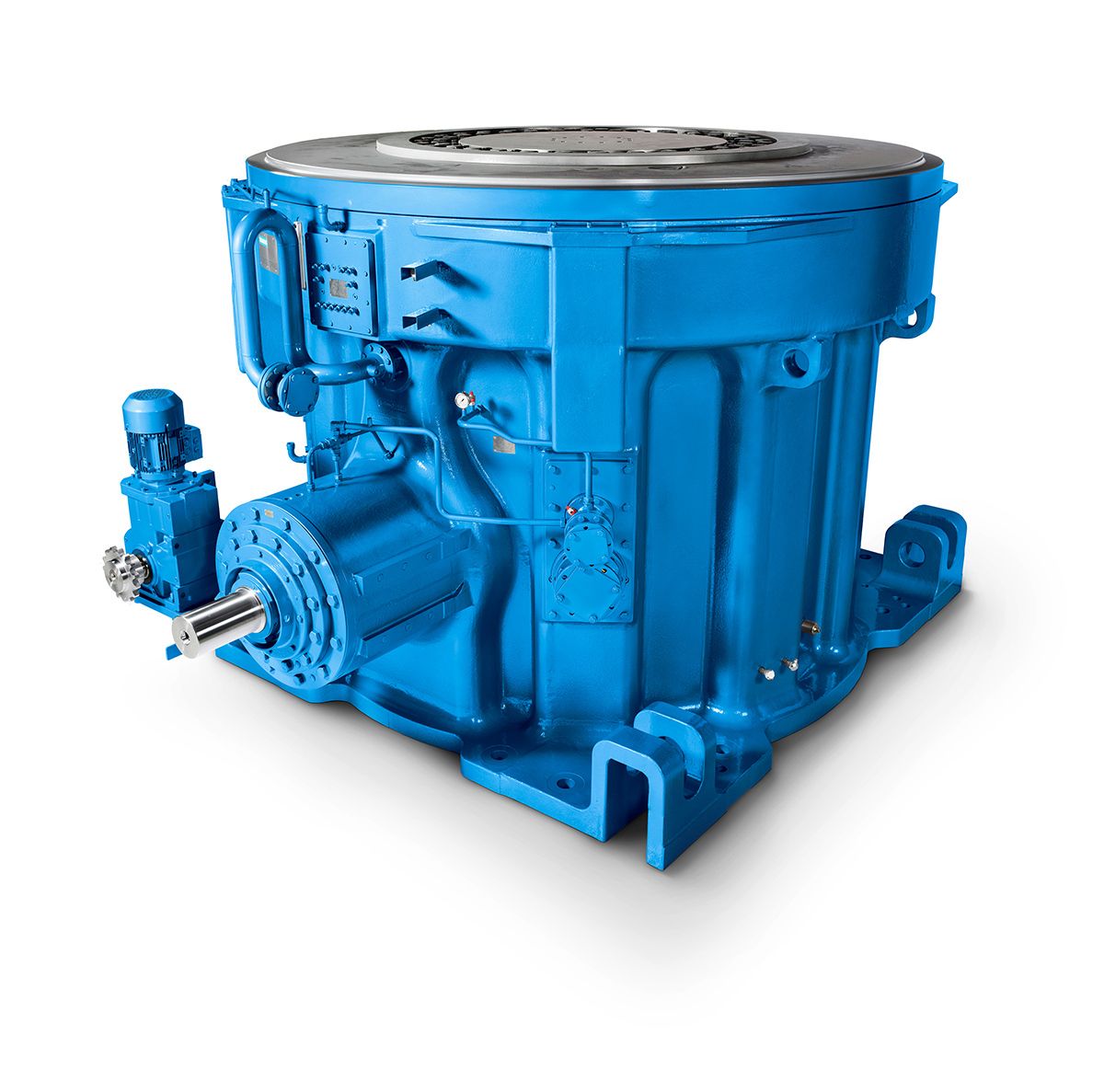
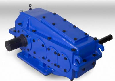
Bevel-helical gear reducer B4 s not possible O r On request When the minimum B4-DH-10-D
In stock
SKU
B4-DH-10-D
$21,964.29
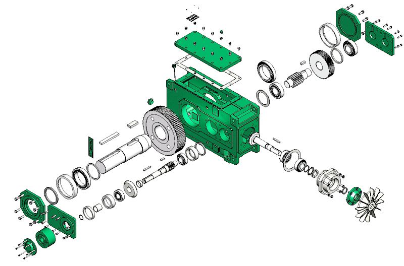
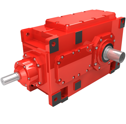
Flender/Flender Gear Units/Bevel-helical gear reducer B4
tter case, further distinction may be drawn between gears with positive or negative offset (see Fig. 2.. Positive offset: the pinion axis is displaced in the direction of the spiral angle of the wheel, the mean helix angle of the
  pinion is larger than that of the wheel, the diameter of the pinion increases when compared to that of an
  equivalent gear set with no offset. Negative offset: the pinion axis is displaced in direction opposite that of the spiral
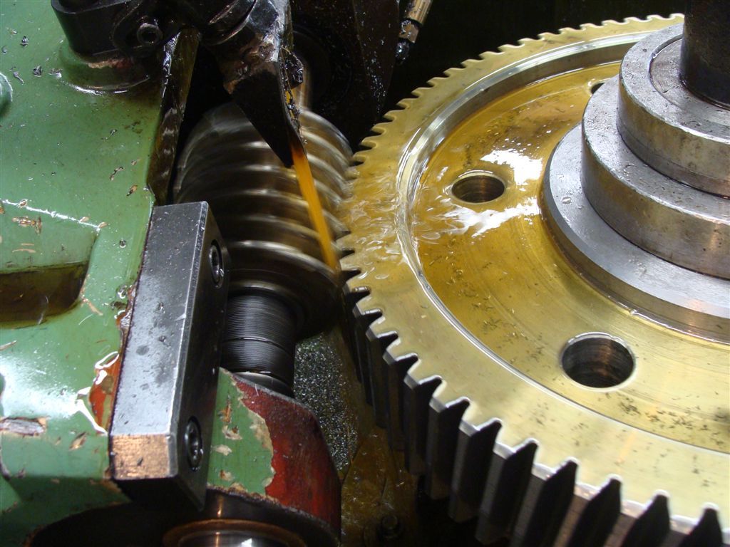
  angle of the wheel, the mean helix angle of the pinion is smaller than that of the wheel, the diameter of the pinion decreases when compared to that of an equivalent gear set with no offset. Positive Offset Negative Offset Fig. 2.3 Denition of hypoid offset2.1 Classication of Bevel Gears 1 Spiral bevel gears, when manufactured in metal-cutting process, can either be produced in single indexing or continuous indexing operations which govern the form of the tooth trace. In the single indexing or face milling method, one tooth slot is cut, the tool is retracted and, after the work piece has been rotated by one pitch, the next tooth slot is cut until all the slots have been done. Since the cutting edges of the tool are arranged in circle, .. on face mill cutter, the tooth traces will show the form of circular arc. In the continuous indexing, or face hobbing method, the rotation of the cutter and that of the bevel gear being produced are coupled in such way that at any time only one blade group passes through particular tooth slot, the next blade group passing through the next slot etc. (see Fig. 2.. Indexing is therefore continuous and all tooth slots are cut quasi-simultaneously. On the basic crown gear, these motions result in tooth trace in the form of an elongated epicycloid. When the epicycloid is being machined, the ratio of the number of teeth to the number of starts on the cutter (number of blade groups) is equivalent to the ratio of the base circle radius to the roll circle radius. An elongated
| Model Type | Bevel-helical gear reducer B4 |
|---|---|
| Gear Type | Bevel Helical Gear |
| Weight (kg) | 1025.000000 |
| Ratio Range | 1 : 100…400 |
| Low Speed Output | Hollow shaft with shrink disk |
| Nominal Torque | 44200 Nm |
| Mounting Arrangements | Horizontal mounting position |
| Manufacturer | PT Flenindo Aditransimisi |
| Country of Manufacture | China |
| Data Sheet & Drawings | Bevel-helical gear reducer B4 s not possible O r On request When the minimum B4-DH-10-D |
Related Products