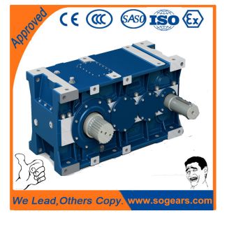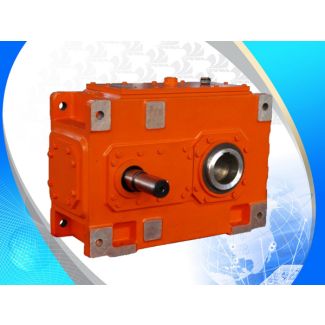
B3-VH19-B to orderrelated documentation Free space for p Bevel-helical gear units B3
In stock
SKU
B3-VH19-B
$150,000.00
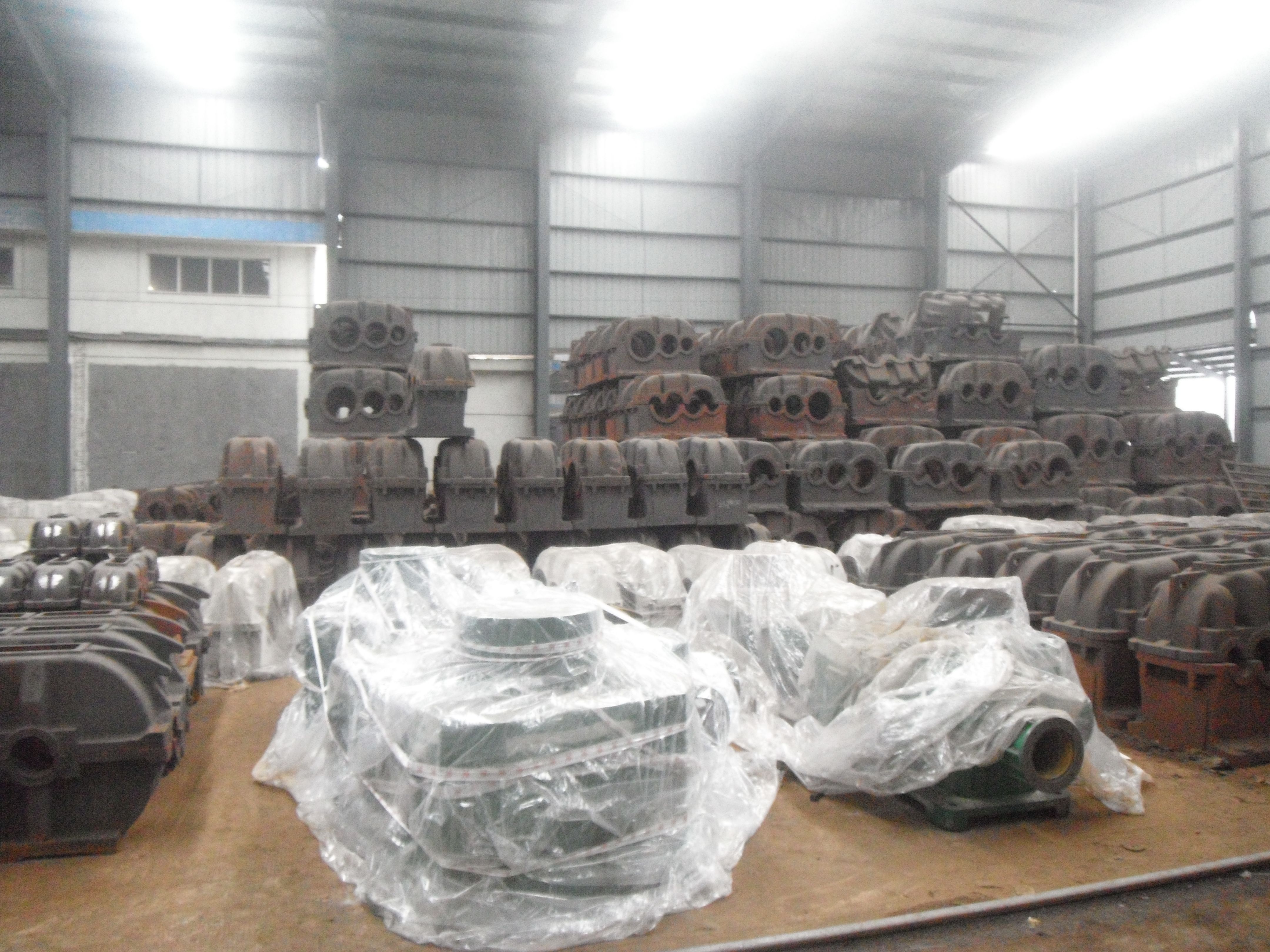
Flender/Flender Gear Units/Bevel-helical gear units B3
onnection KA 3.2 Precisely fitted or adjustable direct attachment as bolted connection (welded construction, roll section, etc.)Top connection using locking pins for installation in attachment design with precisely or larger drilled attachment holes For larger drilled attachment holes, the wheel
  block must be aligned. Subsequently, the wheel block is attached by bolts and should be drilled with the locking pins
  8 supplied. However, this must not be in the area of the attachment bolts []. Alignment is not required for
  precisely drilled attachment holes. 1 Set KA 3.2 comprising of: 8GrubscrewsM1- 1.9ZT 8SafetynutsM1-1DINENISO 7(DIN 8 Discs 1 DIN 6 4 Locking pins 8 DIN EN ISO 8 (DIN , for adjustable connection 8 Locking pins 1.5, for precise connection Longer locking pins are available for thicker plates. Attachment design Hole pattern fo the attachment design for adjustable variant Grub screw M Safety nut M1 Tightening torque 2 Nm Disc 1 Locking pin 8 more options for screwing Pinning is not permitted in this area! Can be factory-glued in the wheel block housing on request. 1 WHEEL BLOCK SYSTEM GENERAL CATALOGUE 0/2 WHEEL BLOCK SYSTEM RB 3 Connection options Pin attachment with alignment option using adjusting washers. Alignment option by replacing the adjusting washers only in dismantled condition. 1 Set BA 3.1 comprising of: 2 Bolts 4h8 2 4 Circlipse 4.7, DIN 4 4 Spacer bolts 1Adjusting washers 4.5,DIN9 Pin connections are available in special design according to the customer drawing.Pin attachment BA 3.1 Pin attachment is adapted to the installation in hollow profiles, floating levers, etc. by means of adjusting washers. Lower support Upper suspension mounting Circlip BoltsAttachment design Spacer bolts Adjusting washers Wheel blockAttachment designHole pattern for torque support acc. tomanufacturersspecifications Holes on both sides only if lubrication is requiredSpacer boltsHoles on both sides only for driven wheel blocks RBA Dime
| Model Type | Bevel-helical gear units B3 |
|---|---|
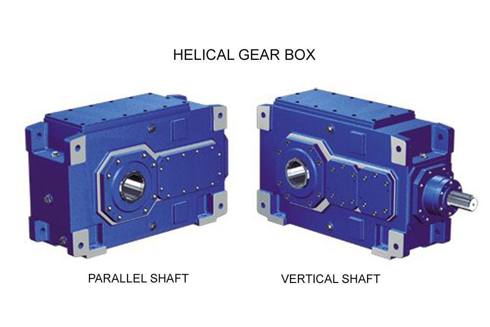
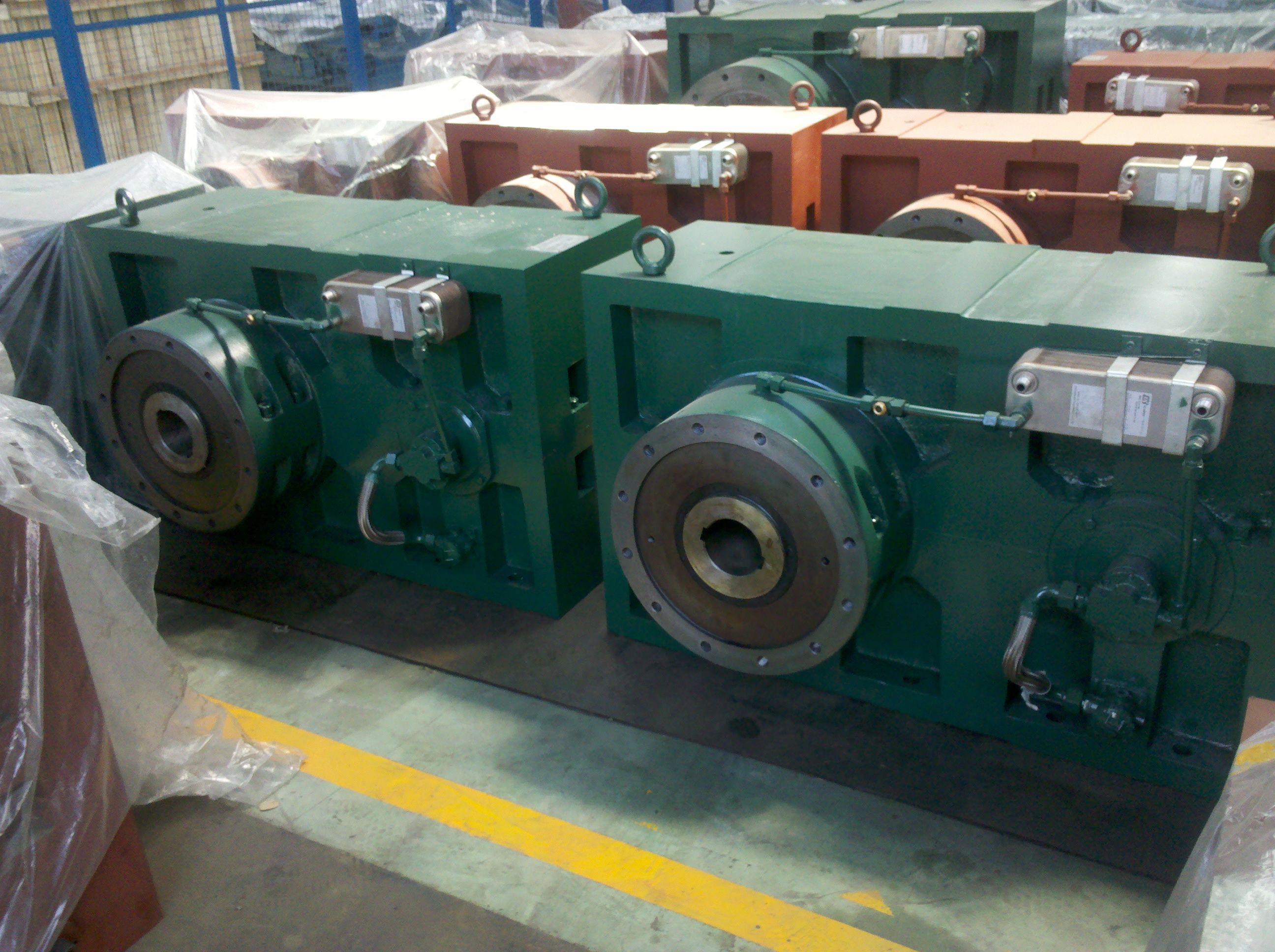
| Gear Type | Bevel Helical Gear |
| Weight (kg) | 7000.000000 |
| Ratio Range | 1 : 12.5…71 |
| Low Speed Output | Solid shaft with parallel key acc. to DIN 6885/1 with reinforced spigot |
| Nominal Torque | 300000 Nm |
| Mounting Arrangements | Horizontal mounting position |
| Manufacturer | A. Friedr. Flender AG & Co. KG |
| Country of Manufacture | Denmark |
| Data Sheet & Drawings | B3-VH19-B to orderrelated documentation Free space for p Bevel-helical gear units B3 |
Related Products