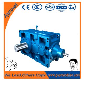

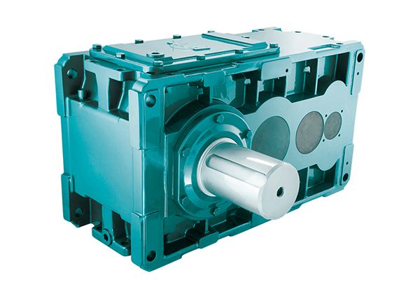
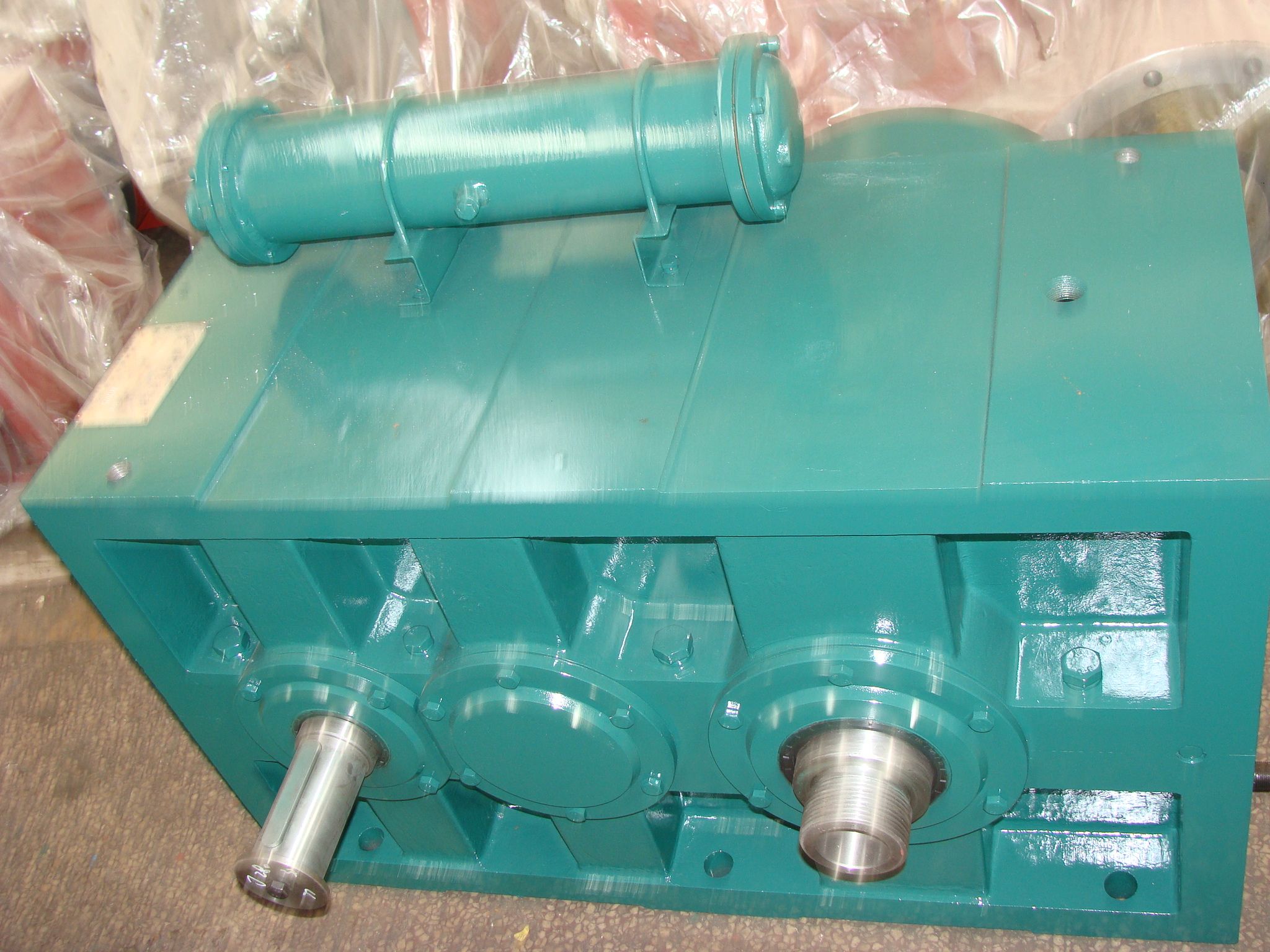
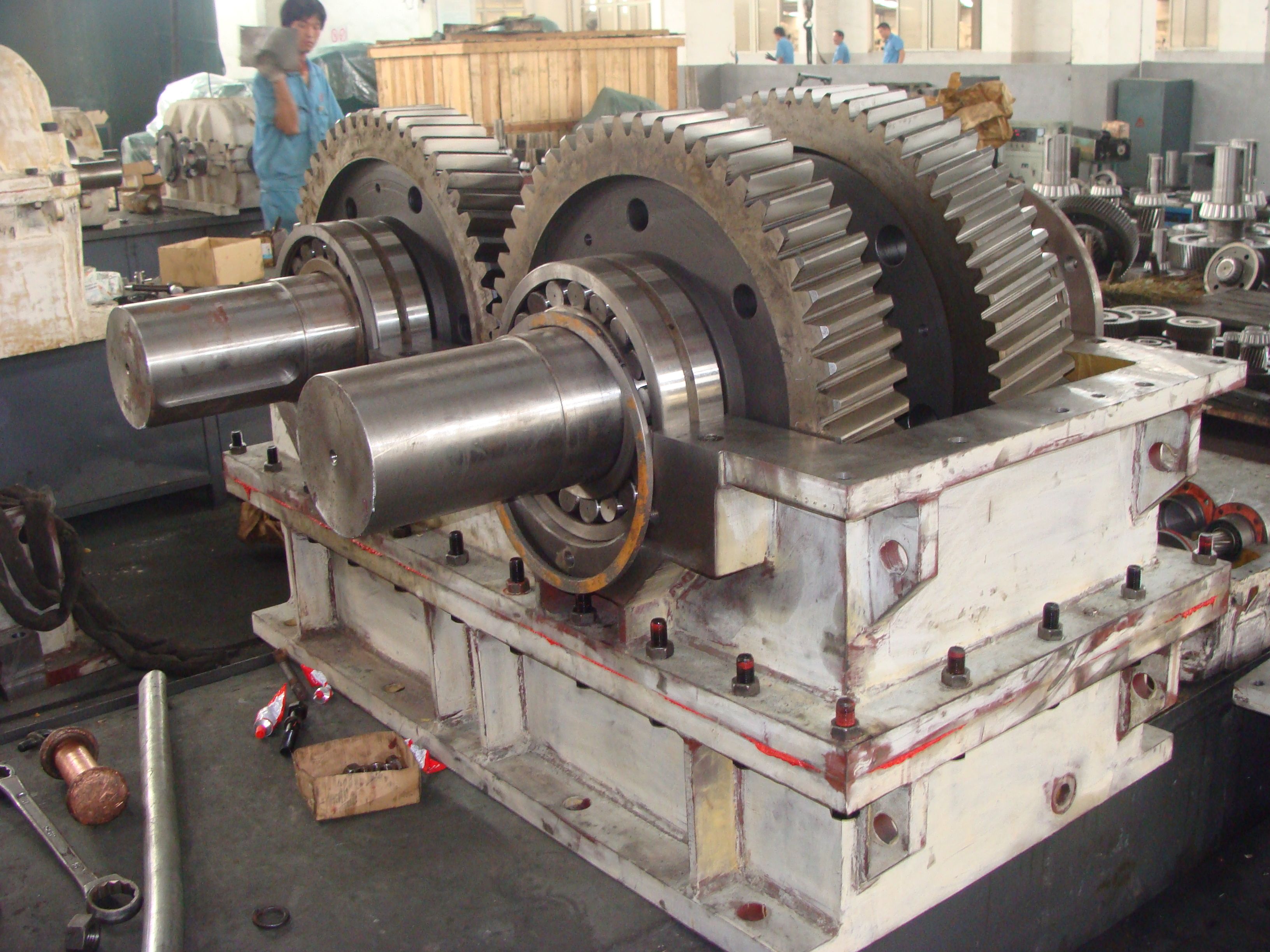
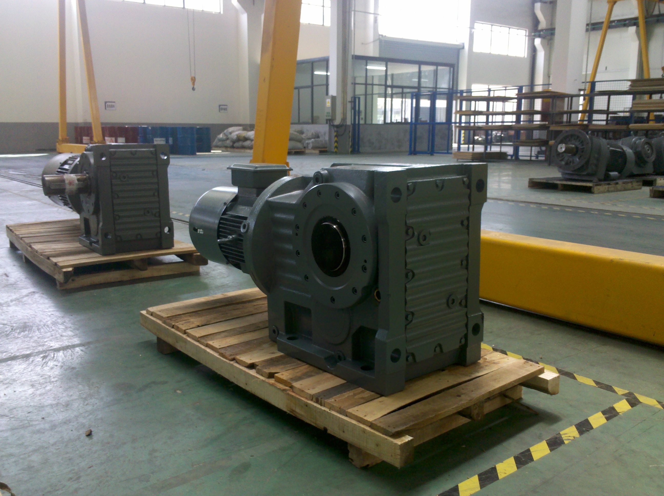
kstop size or larger Flender GmbH Flender MD B3-SV-23-D Bevel-helical speed reduction gearbox B3
Out of stock
SKU
B3-SV-23-D
$257,142.86
Flender/Flender Gear Units/Bevel-helical speed reduction gearbox B3
ols serve for activating and terminating different control processes as well as releasing operations and outputting signals. Technical data Permissible ambient temperature : Type of protection: Protected against overpressure : Switching frequency : max. switching capacity: Material of housing: Diaphragm
  quality: Coupler socket: -3 ... + 1 oc IP 6 up to 1 bar (on the hydraulic part of the
  pressure control) 2 /min 4 2 AC 2 VA 2 2 DC 1 5 DC 0,0 2 DC (alternating current)
  (dual current) Galvanized steel (Fe/Zn 1 ) NBR Polyamide See page 2 for intrinsically safe explosion area 2r---------------------------------------------~------------~----------------~--~ ~ . Friedr. Flender AG, 4 Bocholt, Datum Name: Koster DOA 6~_~_e_l_._o2_8_7_1_1_2_-_o~,T_x __ o_a_1_8_4_1~,_T_e_le_f_ax __ o_2_8_1_1_9_2_5_9_s __ ~_1_3_ .o_4_.1_9_9_s __ ~~~~ .:--------------~ "< (') 0 5 .. Cf) Cll .. -~ ) en Cll 0) ro .. Cll 0) ct\ -.::: Cll ::::> Cll .. en : .. Operating Instructions Edition: April 1 (#)FLENDER Connecting diagram Pressure control ~ -S1 0,5bar ~ To be connected as make or break contact, as required. 5 EN Page 2 of 2 The pressure inside the hydraulic system is increased and decreased repeatedly for checking the switching point. To avoid self-readjustment of the switching point, the integrated turning lock only allows for movement of the screw when certain torque is exceeded . Spare parts It is recommended to keep only complete switches on stock as spare parts. For use in an explosion area, the pressure control can be made intrinsically safe by means of cutoff relay (see example) . Example: Cutoff relay in combination with pressure control (pressure to be monitored 0.5 bar). Non-explosion area Intrinsically safe circuit Explosion area (EEx ia) IIC EN 5 0 ... 5 0 .-------------~~ ----0-,5-b_a_ -+~~~ -8 U1 1 2 3 ~ ...:--7 8 1 1 1 PE L1 2r----------------------------------
| Model Type | Bevel-helical speed reduction gearbox B3 |
|---|---|
| Gear Type | Bevel Helical Gear |
| Weight (kg) | 12000.000000 |
| Ratio Range | 1 : 20…71 |
| Low Speed Output | Solid shaft with parallel key acc. to DIN 6885/1 |
| Nominal Torque | 640000 Nm |
| Mounting Arrangements | Vertical mounting position |
| Manufacturer | flanders electric peru s a c |
| Country of Manufacture | Poland |
| Data Sheet & Drawings | kstop size or larger Flender GmbH Flender MD B3-SV-23-D Bevel-helical speed reduction gearbox B3 |
Related Products