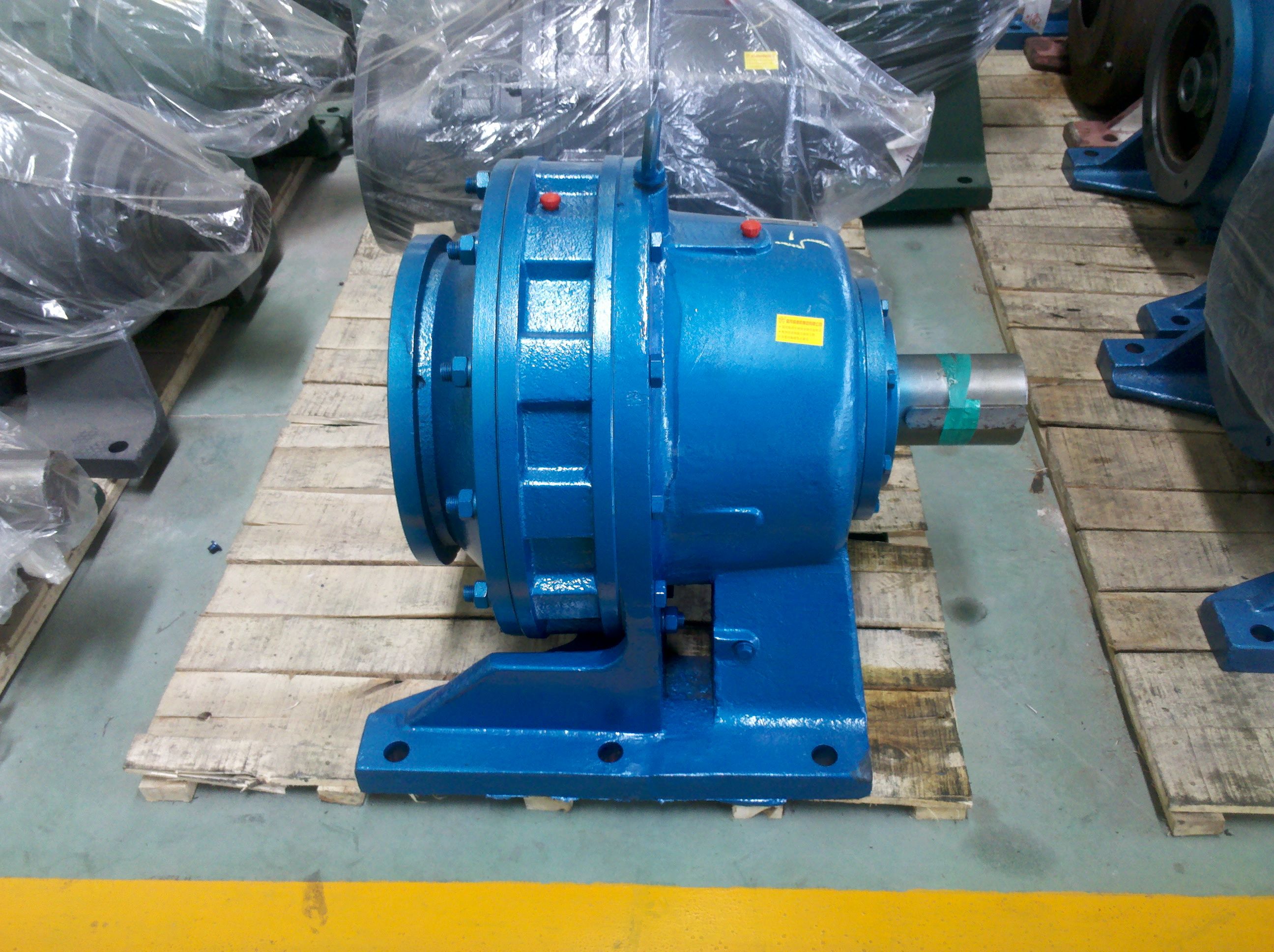
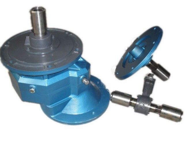
pter For forced lubrication approximately h ca B3-HH21-B Bevel-helical speed reducers B3
In stock
SKU
B3-HH21-B
$197,142.86
Flender/Flender Gear Units/Bevel-helical speed reducers B3
ps as per scheme requirement. All the lamps shall be of cluster LED ype 1. Remote control facilities Shall have transducer to monitor the outputs like motor speed at LCS Facility to accept speed reference from HMI, en gineerin station
  throu gh communication bus. 1. Communication Bus suitabilit . Industrial Ethernet (ProfiNet , Ethernet IP, Modbus over TCP/IP) 1. Analog
  Inputs VFD shall have pr ovision to receive analog inputs from Motor RTD and BTD, Vibrati on Monitors at field.
  These values will be further communicated to Plant DCS on Industrial Ethernet. 1. Drive Features Flying Start Resonance frequenc bypass 1. Signal exchange between Plant PLC and VFD The VFD will need to accept inputs from the Plant PLC .. Start Permissive, speed reference, Fan Shutdown Interlock and Plant -Stop. VFD will in turn give Drive Ready, Running, and Fault inputs to the Plant PLC. VFD will also receive inputs from vibration & temperature monitoring system. These are minimum requirements of signal exchange. Please refer Signal exchange diagram included in this 1 of 1 INDRADHANUSH GAS GRID LIMITED TECHNICAL SPECIFICATION FOR NATURAL GAS COMPRESSOR STATION FOR NORTH EAST GAS GRID PIPELINE PROJECT ______________________________________________________________________________________________ TS NO.: MEC//2UU/0/2/0 Electrical system Chapter-0.0 2, MECON Limited, All Right Reserved Pag 1 of 2 TS for the complete drive system. 1. Operator panel Advance Operator panel Shall be mounted on the front door of the unit. All adjustments to be made with the door closed. Status and Power LEDs viewable through the cove 2. LCD display Display shall be back light ed, enabling viewing in extremes of lighting conditions Displa shall be in alphanumeric (in En glish onl ) 2. Construction features Enclosure protection IP-5or better. Floor mounted, free standing, modular design, Suitable to
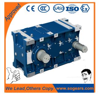
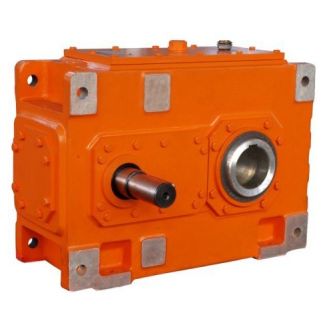
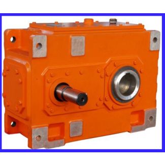
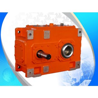
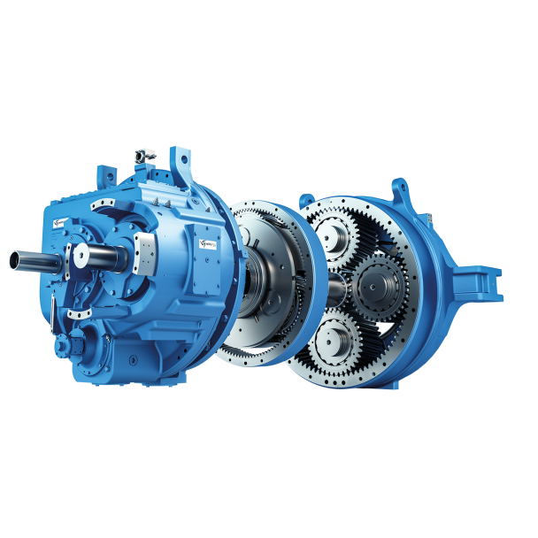
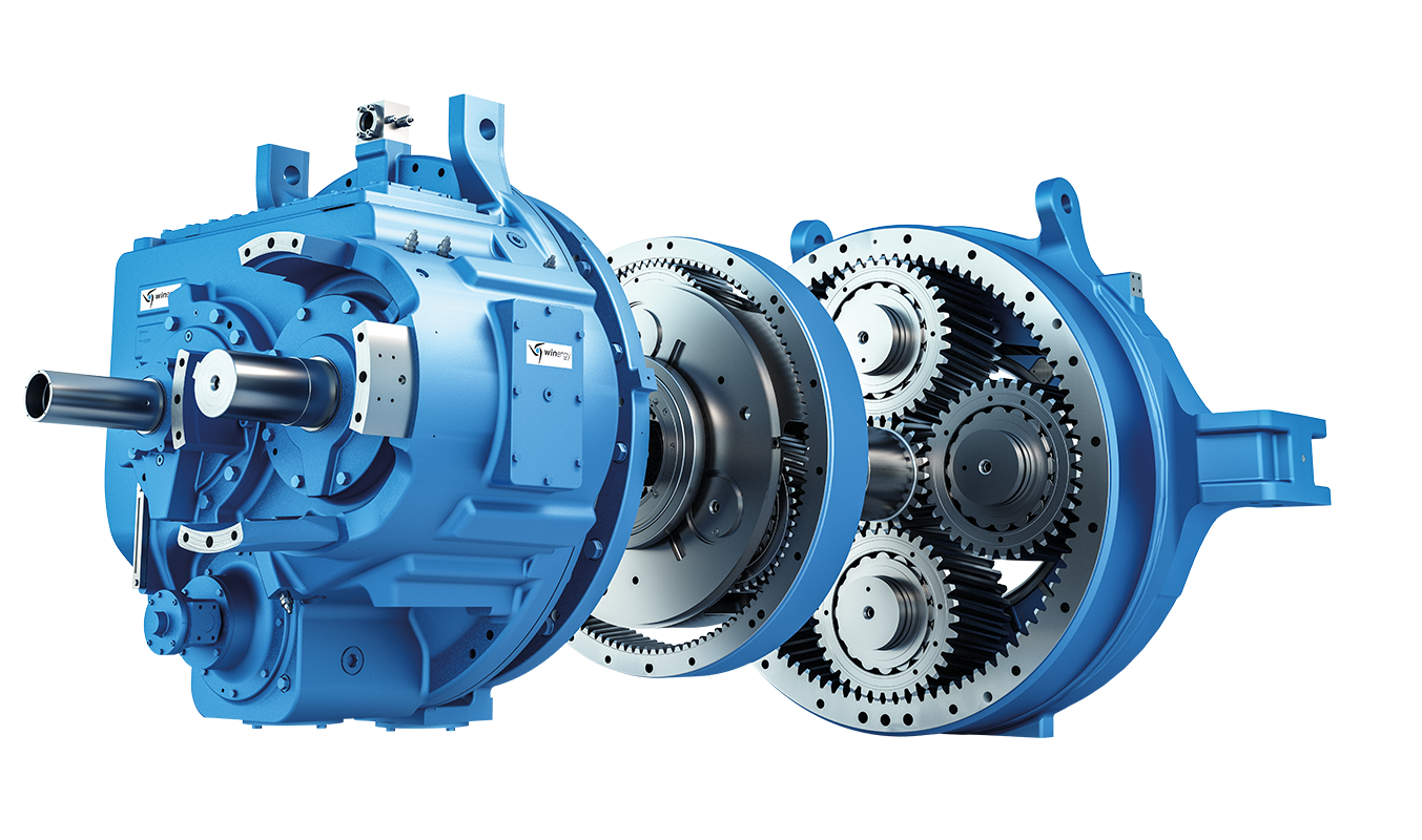
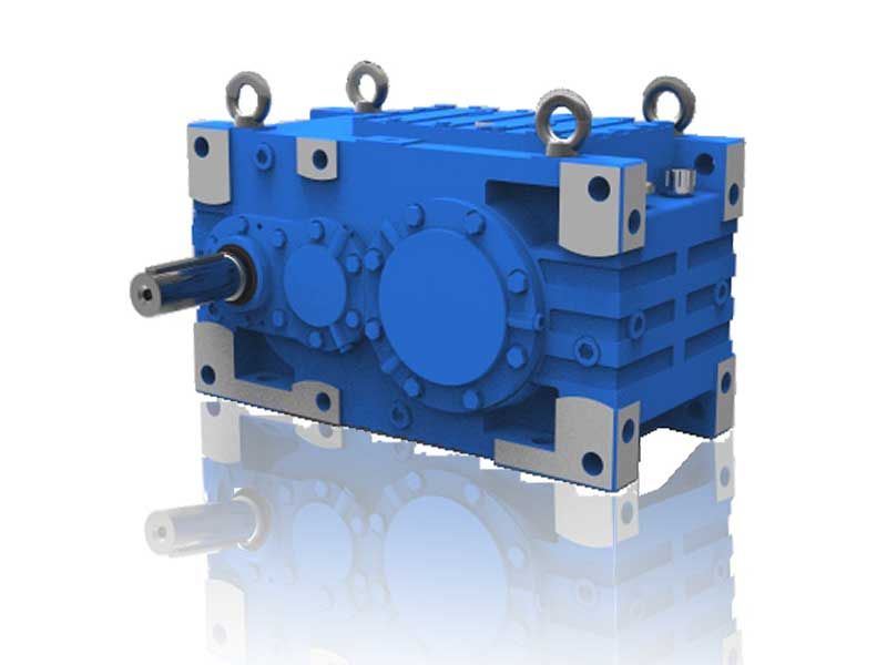
| Model Type | Bevel-helical speed reducers B3 |
|---|---|
| Gear Type | Bevel Helical Gear |
| Weight (kg) | 9200.000000 |
| Ratio Range | 1 : 12.5…71 |
| Low Speed Output | Hollow shaft with keyway acc. to DIN 6885/1 |
| Nominal Torque | 420000 Nm |
| Mounting Arrangements | Horizontal mounting position |
| Manufacturer | Flender Bocholt |
| Country of Manufacture | Germany |
| Data Sheet & Drawings | pter For forced lubrication approximately h ca B3-HH21-B Bevel-helical speed reducers B3 |
Related Products